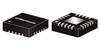
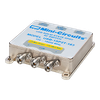
The HSWA2-30DR+ is a 50Ω high isolation SPDT RF switch designed for wireless applications, covering a broad frequency range from DC up to 3000 MHz with low insertion loss. The HSWA2-30DR+ operates on a single supply voltage +3 V. See application note AN-80-006 for +5 V supply voltage. This unit includes an internal CMOS control driver with two-pins control. The switch consumes very low supply current, 8 µA typ. The HSWA2-30DR+ switch is in a very small size and low profile package, 4 x 4 mm and 0.9 mm, respectively FUNCTIONAL DIAGRAM RF Common 50Ω RF1 RF2 50Ω 50Ω CONTROL 1 Internal Control Driver CONTROL 2 REV. K ECO-026795 HSWA2-30DR+ MCL NY 260429 www.minicircuits.com P.O. Box 350166, Brooklyn, NY 11235-0003 (718) 934-4500 sales@minicircuits.c
om PAGE 1 OF 11 SURFACE MOUNT SPDT RF Switch HSWA2-30DR+ 50Ω DC to 3000 MHz Absorptive RF Switch with Internal Driver Single Supply Voltage, +3 V RF ELECTRICAL SPECIFICATIONS, T = +25°C, V = +3 V AMB DD Parameter Condition (MHz) Min. Typ. Max. Units Operating Frequency DC1 3000 MHz 1000 – 0.75 1.0 Insertion Loss2 2000 – 0.95 1.2 dB 3000 – 1.2 1.4 1000 55 64 – Isolation Between Common Port and RF1/RF2 Ports 2000 46 50 – dB 3000 40 44 – 1000 57 63 – Isolation Between RF1 and RF2 Ports 2000 54 60 – dB 3000 40 48 – 1000 – 20 – Return Loss @ Common Port 2000 – 17 – dB 3000 – 14 – 1000 – 20 – Return Loss @ RF1/RF2 Ports 2000 – 18 – dB 3000 – 17 – Input IP2 5-1000 – +80 – dBm 10-1000 – +55 – Input IP33 dBm 1000-3000 – +52 – Input 1 dB Compression3,4 1000 +29 +31 – dBm 1. Lowest Freq. determined by value of coupling capacitors at RF ports. 2. Insertion loss values are de-embedded from test board Loss. 3. Device linearity degrades below 1 MHz. 4. Note absolute maximum ratings for input power. DC ELECTRICAL SPECIFICATIONS Parameter Min. Typ. Max. Units V ,Supply Voltage5 +2.7 +3 +3.3 V DD Supply Current (V = +3 V)6 – 8 20 µA DD Control Voltage Low 0 – +0.3 x V V DD Control Voltage High +0.7 x V – V V DD DD 5. See application note AN-80-006 for +5 V supply voltage. 6. At Control Frequency of 1 kHz. Increases to 21 µA at 10 kHz and 56 µA at 50 kHz typically. SWITCHING SPECIFICATIONS Parameter Min. Typ. Max. Units Switching Time, 50% Control to 90/10% RF – 2.0 – µs Video Feed-Through, 5-1000 MHz7 – – 15 mV P-P 7. Measured with a 1 ns risetime, 0/+3 V pulse and 500 MHz bandwidth. www.minicircuits.com P.O. Box 350166, Brooklyn, NY 11235-0003 (718) 934-4500 sales@minicircuits.c
om PAGE 2 OF 11 SURFACE MOUNT SPDT RF Switch HSWA2-30DR+ 50Ω DC to 3000 MHz Absorptive RF Switch with Internal Driver Single Supply Voltage, +3 V
The HSWA2-30DR+ is a 50Ω high isolation SPDT RF switch designed for wireless applications, covering a broad frequency range from DC up to 3000 MHz with low insertion loss. The HSWA2-30DR+ operates on a single supply voltage +3 V. See application note AN-80-006 for +5 V supply voltage. This unit includes an internal CMOS control driver with two-pins control. The switch consumes very low supply current, 8 µA typ. The HSWA2-30DR+ switch is in a very small size and low profile package, 4 x 4 mm and 0.9 mm, respectively FUNCTIONAL DIAGRAM RF Common 50Ω RF1 RF2 50Ω 50Ω CONTROL 1 Internal Control Driver CONTROL 2 REV. K ECO-026795 HSWA2-30DR+ MCL NY 260429 www.minicircuits.com P.O. Box 350166, Brooklyn, NY 11235-0003 (718) 934-4500 sales@minicircuits.com PAGE 1 OF 11 SURFACE MOUNT SPDT RF Switch HSWA2-30DR+ 50Ω DC to 3000 MHz Absorptive RF Switch with Internal Driver Single Supply Voltage, +3 V RF ELECTRICAL SPECIFICATIONS, T = +25°C, V = +3 V AMB DD Parameter Condition (MHz) Min. Typ. Max. Units Operating Frequency DC1 3000 MHz 1000 – 0.75 1.0 Insertion Loss2 2000 – 0.95 1.2 dB 3000 – 1.2 1.4 1000 55 64 – Isolation Between Common Port and RF1/RF2 Ports 2000 46 50 – dB 3000 40 44 – 1000 57 63 – Isolation Between RF1 and RF2 Ports 2000 54 60 – dB 3000 40 48 – 1000 – 20 – Return Loss @ Common Port 2000 – 17 – dB 3000 – 14 – 1000 – 20 – Return Loss @ RF1/RF2 Ports 2000 – 18 – dB 3000 – 17 – Input IP2 5-1000 – +80 – dBm 10-1000 – +55 – Input IP33 dBm 1000-3000 – +52 – Input 1 dB Compression3,4 1000 +29 +31 – dBm 1. Lowest Freq. determined by value of coupling capacitors at RF ports. 2. Insertion loss values are de-embedded from test board Loss. 3. Device linearity degrades below 1 MHz. 4. Note absolute maximum ratings for input power. DC ELECTRICAL SPECIFICATIONS Parameter Min. Typ. Max. Units V ,Supply Voltage5 +2.7 +3 +3.3 V DD Supply Current (V = +3 V)6 – 8 20 µA DD Control Voltage Low 0 – +0.3 x V V DD Control Voltage High +0.7 x V – V V DD DD 5. See application note AN-80-006 for +5 V supply voltage. 6. At Control Frequency of 1 kHz. Increases to 21 µA at 10 kHz and 56 µA at 50 kHz typically. SWITCHING SPECIFICATIONS Parameter Min. Typ. Max. Units Switching Time, 50% Control to 90/10% RF – 2.0 – µs Video Feed-Through, 5-1000 MHz7 – – 15 mV P-P 7. Measured with a 1 ns risetime, 0/+3 V pulse and 500 MHz bandwidth. www.minicircuits.com P.O. Box 350166, Brooklyn, NY 11235-0003 (718) 934-4500 sales@minicircuits.com PAGE 2 OF 11 SURFACE MOUNT SPDT RF Switch HSWA2-30DR+ 50Ω DC to 3000 MHz Absorptive RF Switch with Internal Driver Single Supply Voltage, +3 V