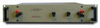
Solar Electronics Co. LISN 9632-50-TS-50-N

Description
The 9632-50-TS-50-N is LISN equipment from Solar. A line impedance stabilization network (LISN) device is something engineers use to test radiofrequency (RF) emission and susceptibility. During an electronic equipment test, engineers place the LISN device between an alternating current or direct current power source and the equipment under test. Additional Features: Inductance µH: 50 0.25µf coupling caps Current Amps: 50 Line/Ground Voltage, 50-60 Hz: 270 Line/Ground Voltage, 400 Hz: 130 Case Size: 10.06" x 9.0" x 13.12" (25.72 cm x 22.86 cm x 33.34 cm) Circuit: Single Frequency Range: 10 KHz-50 MHz, high wattage for GM spec The Solar Electronics LISNs use a series inductor between the test sample and the power source to provide the impedance-versus-fre quency characteristic. A coaxial connector with dc isolation is provided for connection to the associated frequency selective EMI meter. The power source end of the inductor is bypassed to ground. Due to the large current-carrying capability of some LISNs, it is not always practical to use a switch for changing inductance values. Instead, some models are equipped with a high current pin plug-and-jack combination for quickly connecting and disconnecting a network and substituting another. This nylon insulated pin plug and jack arrangement is a safety feature, well isolated from inadvertent short circuits, providing protection to operating personnel. EMI specifications require one LISN in each ungrounded power lead. Even though the neutral is considered “ground,” if it is not connected to chassis inside the unit under test, the lead must be tested with an LISN. Therefore, use two LISNs in dc or single phase ac applications, three LISNs for delta-connected three phase circuits, and four LISNs for ‘Y’ connected three phase circuits. Application When measuring conducted radio interference voltages from active power lines to ground, it is essential to know the line impedance so that repeatable tests can be made by more than one laboratory. Artificial line impedances are specified in MIL-STD-462, V.D.E., C.I.S.P.R., C22.4, NACSEM 5100, ANSI C63.2 and other EMI specifications. The characteristic impedance of the five microhenry and 50 microhenry LISNs brackets the mean value of power line impedance which has been measured by independent researchers. These two inductance values in parallel with the 50 ohms of the EMI meter fall between the minimum and maximum line impedance values which have been measured. The mean value would be represented by a twenty microhenry inductor in parallel with 100 ohms.
Description
The 9632-50-TS-50-N is LISN equipment from Solar. A line impedance stabilization network (LISN) device is something engineers use to test radiofrequency (RF) emission and susceptibility. During an electronic equipment test, engineers place the LISN device between an alternating current or direct current power source and the equipment under test. Additional Features: Inductance µH: 50 0.25µf coupling caps Current Amps: 50 Line/Ground Voltage, 50-60 Hz: 270 Line/Ground Voltage, 400 Hz: 130 Case Size: 10.06" x 9.0" x 13.12" (25.72 cm x 22.86 cm x 33.34 cm) Circuit: Single Frequency Range: 10 KHz-50 MHz, high wattage for GM spec The Solar Electronics LISNs use a series inductor between the test sample and the power source to provide the impedance-versus-fre quency characteristic. A coaxial connector with dc isolation is provided for connection to the associated frequency selective EMI meter. The power source end of the inductor is bypassed to ground. Due to the large current-carrying capability of some LISNs, it is not always practical to use a switch for changing inductance values. Instead, some models are equipped with a high current pin plug-and-jack combination for quickly connecting and disconnecting a network and substituting another. This nylon insulated pin plug and jack arrangement is a safety feature, well isolated from inadvertent short circuits, providing protection to operating personnel. EMI specifications require one LISN in each ungrounded power lead. Even though the neutral is considered “ground,” if it is not connected to chassis inside the unit under test, the lead must be tested with an LISN. Therefore, use two LISNs in dc or single phase ac applications, three LISNs for delta-connected three phase circuits, and four LISNs for ‘Y’ connected three phase circuits. Application When measuring conducted radio interference voltages from active power lines to ground, it is essential to know the line impedance so that repeatable tests can be made by more than one laboratory. Artificial line impedances are specified in MIL-STD-462, V.D.E., C.I.S.P.R., C22.4, NACSEM 5100, ANSI C63.2 and other EMI specifications. The characteristic impedance of the five microhenry and 50 microhenry LISNs brackets the mean value of power line impedance which has been measured by independent researchers. These two inductance values in parallel with the 50 ohms of the EMI meter fall between the minimum and maximum line impedance values which have been measured. The mean value would be represented by a twenty microhenry inductor in parallel with 100 ohms.

Suppliers

Company
Product
Description
Supplier Links
The 9632-50-TS-50-N is LISN equipment from Solar. A line impedance stabilization network (LISN) device is something engineers use to test radiofrequency (RF) emission and susceptibility. During an electronic equipment test, engineers place the LISN device between an alternating current or direct current power source and the equipment under test. Additional Features: Inductance µH: 50 0.25µf coupling caps Current Amps: 50 Line/Ground Voltage, 50-60 Hz: 270 Line/Ground Voltage, 400 Hz: 130 Case Size: 10.06" x 9.0" x 13.12" (25.72 cm x 22.86 cm x 33.34 cm) Circuit: Single Frequency Range: 10 KHz-50 MHz, high wattage for GM spec The Solar Electronics LISNs use a series inductor between the test sample and the power source to provide the impedance-versus-fre quency characteristic. A coaxial connector with dc isolation is provided for connection to the associated frequency selective EMI meter. The power source end of the inductor is bypassed to ground. Due to the large current-carrying capability of some LISNs, it is not always practical to use a switch for changing inductance values. Instead, some models are equipped with a high current pin plug-and-jack combination for quickly connecting and disconnecting a network and substituting another. This nylon insulated pin plug and jack arrangement is a safety feature, well isolated from inadvertent short circuits, providing protection to operating personnel. EMI specifications require one LISN in each ungrounded power lead. Even though the neutral is considered “ground,” if it is not connected to chassis inside the unit under test, the lead must be tested with an LISN. Therefore, use two LISNs in dc or single phase ac applications, three LISNs for delta-connected three phase circuits, and four LISNs for ‘Y’ connected three phase circuits. Application When measuring conducted radio interference voltages from active power lines to ground, it is essential to know the line impedance so that repeatable tests can be made by more than one laboratory. Artificial line impedances are specified in MIL-STD-462, V.D.E., C.I.S.P.R., C22.4, NACSEM 5100, ANSI C63.2 and other EMI specifications. The characteristic impedance of the five microhenry and 50 microhenry LISNs brackets the mean value of power line impedance which has been measured by independent researchers. These two inductance values in parallel with the 50 ohms of the EMI meter fall between the minimum and maximum line impedance values which have been measured. The mean value would be represented by a twenty microhenry inductor in parallel with 100 ohms.
The 9632-50-TS-50-N is LISN equipment from Solar. A line impedance stabilization network (LISN) device is something engineers use to test radiofrequency (RF) emission and susceptibility. During an electronic equipment test, engineers place the LISN device between an alternating current or direct current power source and the equipment under test.

Additional Features:

  • Inductance µH: 50
  • 0.25µf coupling caps
  • Current Amps: 50
  • Line/Ground Voltage, 50-60 Hz: 270
  • Line/Ground Voltage, 400 Hz: 130
  • Case Size: 10.06" x 9.0" x 13.12" (25.72 cm x 22.86 cm x 33.34 cm)
  • Circuit: Single
  • Frequency Range: 10 KHz-50 MHz, high wattage for GM spec

The Solar Electronics LISNs use a series inductor between the test sample and the power source to provide the impedance-versus-frequency characteristic. A coaxial connector with dc isolation is provided for connection to the associated frequency selective EMI meter. The power source end of the inductor is bypassed to ground.

Due to the large current-carrying capability of some LISNs, it is not always practical to use a switch for changing inductance values. Instead, some models are equipped with a high current pin plug-and-jack combination for quickly connecting and disconnecting a network and substituting another. This nylon insulated pin plug and jack arrangement is a safety feature, well isolated from inadvertent short circuits, providing protection to operating personnel.

EMI specifications require one LISN in each ungrounded power lead. Even though the neutral is considered “ground,” if it is not connected to chassis inside the unit under test, the lead must be tested with an LISN. Therefore, use two LISNs in dc or single phase ac applications, three LISNs for delta-connected three phase circuits, and four LISNs for ‘Y’ connected three phase circuits.

Application
When measuring conducted radio interference voltages from active power lines to ground, it is essential to know the line impedance so that repeatable tests can be made by more than one laboratory. Artificial line impedances are specified in MIL-STD-462, V.D.E., C.I.S.P.R., C22.4, NACSEM 5100, ANSI C63.2 and other EMI specifications.

The characteristic impedance of the five microhenry and 50 microhenry LISNs brackets the mean value of power line impedance which has been measured by independent researchers. These two inductance values in parallel with the 50 ohms of the EMI meter fall between the minimum and maximum line impedance values which have been measured. The mean value would be represented by a twenty microhenry inductor in parallel with 100 ohms.

Supplier's Site

Technical Specifications

  ValueTronics International, Inc.
Product Category Impedance Matching Networks
Product Number 9632-50-TS-50-N
Product Name LISN
Frequency 50 MHz
Unlock Full Specs
to access all available technical data

Similar Products

Impedance Matching Transformer - Model MT56R - Krohn-Hite Corporation
Specs
Modes of Operation Manual
Frequency 3.00E-5 to 5 MHz
Power 75 watts
View Details
Navio™ Digital Matching Network -  - Advanced Energy Industries, Inc.
Advanced Energy Industries, Inc.
Specs
Modes of Operation Automatic
Cooling Forced Air
Frequency 13.56 to 60 MHz
View Details
Match Pro Impedance Matching Networks - CPM1000 - Comdel, Inc.
Specs
Modes of Operation Manual; Automatic
Cooling Forced Air (optional feature); Water Cooling (optional feature)
View Details
Reference Impedance Network - ES4152/ES4153 - Wayne Kerr Electronics
Specs
Phase Single Phase; Three Phase (optional feature)
View Details