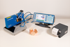
The selected measurement instrument (LMI 200, Digital Indicator, etc..) once turned on is inserted into the 3rd axis probe body and locked in.
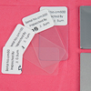
Insert 3rd axis probe into the Verification Master.
The reading on the measurement instrument should be “.00 +/-.01 mm”
If readings beyond acceptable limits are observed, simply reset zero on the measurement instrument.
Shipped with CE125-95
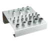
NIST traceable certification documents.
Note: The CE125-95 Verification Master checks 3rd Axis Probes with 1.25” dia shafts and 95.0 mm part / surface offsets.
- The selected measurement instrument (LMI 200, Digital Indicator, etc..) once turned on is inserted into the 3rd axis probe body and locked in.
- Insert 3rd axis probe into the Verification Master.
- The reading on the measurement instrument should be “.00 +/-.01 mm”
- If readings beyond acceptable limits are observed, simply reset zero on the measurement instrument.
Shipped with CE125-95
NIST traceable certification documents.
Note: The CE125-95 Verification Master checks 3rd Axis Probes with 1.25” dia shafts and 95.0 mm part / surface offsets.