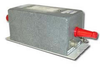
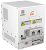
The 6338-5-PJ-50-BNC is a used LISN from Solar. A line impedance stabilization network (LISN) device is something engineers use to test radiofrequency (RF) emission and susceptibility. During an electronic equipment test, engineers place the LISN device between an alternating current or direct current power source and the equipment under test.
Additional Features:
Current Amps: 50
Inductance μH: 5
Line/Ground Voltage 50-60 Hz: 270
Line/Ground Voltage 400 Hz: 130
Circuit: Single
Frequency Range: 150 kHz- 65 MHz
Terminals: Plug and Jack
The Solar Electronics LISNs use a series inductor between the test sample and the power source to provide the impedance-versus-fre
quency characteristic. A coaxial connector with d.c. isolation is provided for connection to the associated frequency selective EMI meter. The power source end of the inductor is bypassed to ground.
When measuring conducted radio interference voltages from active power lines to ground, it is essential to know the line impedance so that repeatable tests can be made by more than one laboratory. Artificial line impedances are specified in MIL-STD-462, V.D.E., C.I.S.P.R., C22.4, NACSEM 5100, ANSI C63.2 and other EMI specifications.
The characteristic impedance of the five microhenry and 50 microhenry LISNs brackets the mean value of power line impedance which has been measured by independent researchers. These two inductance values in parallel with the 50 ohms of the EMI meter fall between the minimum and maximum line impedance values which have been measured. The mean value would be represented by a twenty microhenry inductor in parallel with 100 ohms.
The 6338-5-PJ-50-BNC is a used LISN from Solar. A line impedance stabilization network (LISN) device is something engineers use to test radiofrequency (RF) emission and susceptibility. During an electronic equipment test, engineers place the LISN device between an alternating current or direct current power source and the equipment under test.
Additional Features:
- Current Amps: 50
- Inductance μH: 5
- Line/Ground Voltage 50-60 Hz: 270
- Line/Ground Voltage 400 Hz: 130
- Circuit: Single
- Frequency Range: 150 kHz- 65 MHz
- Terminals: Plug and Jack
The Solar Electronics LISNs use a series inductor between the test sample and the power source to provide the impedance-versus-frequency characteristic. A coaxial connector with d.c. isolation is provided for connection to the associated frequency selective EMI meter. The power source end of the inductor is bypassed to ground.
When measuring conducted radio interference voltages from active power lines to ground, it is essential to know the line impedance so that repeatable tests can be made by more than one laboratory. Artificial line impedances are specified in MIL-STD-462, V.D.E., C.I.S.P.R., C22.4, NACSEM 5100, ANSI C63.2 and other EMI specifications.
The characteristic impedance of the five microhenry and 50 microhenry LISNs brackets the mean value of power line impedance which has been measured by independent researchers. These two inductance values in parallel with the 50 ohms of the EMI meter fall between the minimum and maximum line impedance values which have been measured. The mean value would be represented by a twenty microhenry inductor in parallel with 100 ohms.