Electro Standards Laboratories 4-Channel E1 TX/RX BNC A/B Network Switch Model 8036

Description
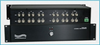
SPECIFICATIONS: PORT CONNECTORS: (24) BNC female connectors. Each of the 4 channels has two COMMON connectors (TX and RX), two "A" connectors (TX and RX), and two "B" connectors (TX and RX). FRONT PANEL CONTROL: (1) Rotary Switch on front panel selects A or B. DISPLAY: (2) Front panel LED's display and verify switch position. POWER: The switch is manually operated and requires power for the LED display. UL approved 100VAC/240VAC, 50Hz/60Hz wall mount power module supplies 12 VDC, 500 mA to the unit. Has 2-prong, US, non-polarized plug. DIMENSIONS: Rackmount 19.0" W x 3.5" H x 8.0"D. (48.3 x 8.9 x 20.3 cm) WEIGHT: Approximately 5.5 lbs. (2.5 Kg) E1 TX/RX BNC NETWORK APPLICATION: The drawing illustrates simultaneous switching of four channels of E1 TX/RX BNC interface. Each channel has an RX and TX BNC connector for the A port, B port, and COMMON port. Four E1 COMMON devices have access to four E1 devices connected to Port A, or by switching to the B position have access to four other E1 devices. The Model 8036 4-Channel E1 A/B Switch allows the user to simultaneously switch all four E1 COMMON channels to four "A" E1 devices or four "B" E1 devices. The switch is manually operated via one front panel rotary switch, requiring power only to operate the LED's that display switch position. The E1 communications interface using two BNC coaxial connections (TX and RX) is typically an unbalanced interface over 75 Ohm coaxial cables. The Model 8036 switches both the center conductor and shield (Tip and Ring, respectively). FEATURES: Each of four channels allows quick connection to any one of two E1 devices from one COMMON E1 channel. Manual operation via front-panel rotary switch. Simultaneously switches all four channels via front-panel rotary switch. Switches both the shield and center conductor of the coaxial interface. Front panel LED's display and verify switch position. High quality sealed switch with self-wiping low impedance contacts. Eliminates the need to plug and unplug cables. Attractive anodized black box packaging provides EMI/RFI shielding. Custom length BNC cables available for your switch installation. Lifetime guarantee against manufacturing defects.
Datasheet
Description
SPECIFICATIONS: PORT CONNECTORS: (24) BNC female connectors. Each of the 4 channels has two COMMON connectors (TX and RX), two "A" connectors (TX and RX), and two "B" connectors (TX and RX). FRONT PANEL CONTROL: (1) Rotary Switch on front panel selects A or B. DISPLAY: (2) Front panel LED's display and verify switch position. POWER: The switch is manually operated and requires power for the LED display. UL approved 100VAC/240VAC, 50Hz/60Hz wall mount power module supplies 12 VDC, 500 mA to the unit. Has 2-prong, US, non-polarized plug. DIMENSIONS: Rackmount 19.0" W x 3.5" H x 8.0"D. (48.3 x 8.9 x 20.3 cm) WEIGHT: Approximately 5.5 lbs. (2.5 Kg) E1 TX/RX BNC NETWORK APPLICATION: The drawing illustrates simultaneous switching of four channels of E1 TX/RX BNC interface. Each channel has an RX and TX BNC connector for the A port, B port, and COMMON port. Four E1 COMMON devices have access to four E1 devices connected to Port A, or by switching to the B position have access to four other E1 devices. The Model 8036 4-Channel E1 A/B Switch allows the user to simultaneously switch all four E1 COMMON channels to four "A" E1 devices or four "B" E1 devices. The switch is manually operated via one front panel rotary switch, requiring power only to operate the LED's that display switch position. The E1 communications interface using two BNC coaxial connections (TX and RX) is typically an unbalanced interface over 75 Ohm coaxial cables. The Model 8036 switches both the center conductor and shield (Tip and Ring, respectively). FEATURES: Each of four channels allows quick connection to any one of two E1 devices from one COMMON E1 channel. Manual operation via front-panel rotary switch. Simultaneously switches all four channels via front-panel rotary switch. Switches both the shield and center conductor of the coaxial interface. Front panel LED's display and verify switch position. High quality sealed switch with self-wiping low impedance contacts. Eliminates the need to plug and unplug cables. Attractive anodized black box packaging provides EMI/RFI shielding. Custom length BNC cables available for your switch installation. Lifetime guarantee against manufacturing defects.
Datasheet

Suppliers

Company
Product
Description
Supplier Links
4-Channel E1 TX/RX BNC A/B Network Switch - Model 8036 - Electro Standards Laboratories
Cranston, RI, USA
4-Channel E1 TX/RX BNC A/B Network Switch
Model 8036
4-Channel E1 TX/RX BNC A/B Network Switch Model 8036
SPECIFICATIONS: PORT CONNECTORS: (24) BNC female connectors. Each of the 4 channels has two COMMON connectors (TX and RX), two "A" connectors (TX and RX), and two "B" connectors (TX and RX). FRONT PANEL CONTROL: (1) Rotary Switch on front panel selects A or B. DISPLAY: (2) Front panel LED's display and verify switch position. POWER: The switch is manually operated and requires power for the LED display. UL approved 100VAC/240VAC, 50Hz/60Hz wall mount power module supplies 12 VDC, 500 mA to the unit. Has 2-prong, US, non-polarized plug. DIMENSIONS: Rackmount 19.0" W x 3.5" H x 8.0"D. (48.3 x 8.9 x 20.3 cm) WEIGHT: Approximately 5.5 lbs. (2.5 Kg) E1 TX/RX BNC NETWORK APPLICATION: The drawing illustrates simultaneous switching of four channels of E1 TX/RX BNC interface. Each channel has an RX and TX BNC connector for the A port, B port, and COMMON port. Four E1 COMMON devices have access to four E1 devices connected to Port A, or by switching to the B position have access to four other E1 devices. The Model 8036 4-Channel E1 A/B Switch allows the user to simultaneously switch all four E1 COMMON channels to four "A" E1 devices or four "B" E1 devices. The switch is manually operated via one front panel rotary switch, requiring power only to operate the LED's that display switch position. The E1 communications interface using two BNC coaxial connections (TX and RX) is typically an unbalanced interface over 75 Ohm coaxial cables. The Model 8036 switches both the center conductor and shield (Tip and Ring, respectively). FEATURES: Each of four channels allows quick connection to any one of two E1 devices from one COMMON E1 channel. Manual operation via front-panel rotary switch. Simultaneously switches all four channels via front-panel rotary switch. Switches both the shield and center conductor of the coaxial interface. Front panel LED's display and verify switch position. High quality sealed switch with self-wiping low impedance contacts. Eliminates the need to plug and unplug cables. Attractive anodized black box packaging provides EMI/RFI shielding. Custom length BNC cables available for your switch installation. Lifetime guarantee against manufacturing defects.
SPECIFICATIONS:

  • PORT CONNECTORS: (24) BNC female connectors. Each of the 4 channels has two COMMON connectors (TX and RX), two "A" connectors (TX and RX), and two "B" connectors (TX and RX).
  • FRONT PANEL CONTROL: (1) Rotary Switch on front panel selects A or B.
  • DISPLAY: (2) Front panel LED's display and verify switch position.
  • POWER: The switch is manually operated and requires power for the LED display. UL approved 100VAC/240VAC, 50Hz/60Hz wall mount power module supplies 12 VDC, 500 mA to the unit. Has 2-prong, US, non-polarized plug.
  • DIMENSIONS: Rackmount 19.0" W x 3.5" H x 8.0"D. (48.3 x 8.9 x 20.3 cm)
  • WEIGHT: Approximately 5.5 lbs. (2.5 Kg)

E1 TX/RX BNC NETWORK APPLICATION: The drawing illustrates simultaneous switching of four channels of E1 TX/RX BNC interface. Each channel has an RX and TX BNC connector for the A port, B port, and COMMON port. Four E1 COMMON devices have access to four E1 devices connected to Port A, or by switching to the B position have access to four other E1 devices.

The Model 8036 4-Channel E1 A/B Switch allows the user to simultaneously switch all four E1 COMMON channels to four "A" E1 devices or four "B" E1 devices. The switch is manually operated via one front panel rotary switch, requiring power only to operate the LED's that display switch position. The E1 communications interface using two BNC coaxial connections (TX and RX) is typically an unbalanced interface over 75 Ohm coaxial cables. The Model 8036 switches both the center conductor and shield (Tip and Ring, respectively).

FEATURES:

  • Each of four channels allows quick connection to any one of two E1 devices from one COMMON E1 channel.
  • Manual operation via front-panel rotary switch.
  • Simultaneously switches all four channels via front-panel rotary switch.
  • Switches both the shield and center conductor of the coaxial interface.
  • Front panel LED's display and verify switch position.
  • High quality sealed switch with self-wiping low impedance contacts.
  • Eliminates the need to plug and unplug cables.
  • Attractive anodized black box packaging provides EMI/RFI shielding.
  • Custom length BNC cables available for your switch installation.
  • Lifetime guarantee against manufacturing defects.
Supplier's Site Datasheet

Technical Specifications

  Electro Standards Laboratories
Product Category Network Equipment
Product Number Model 8036
Product Name 4-Channel E1 TX/RX BNC A/B Network Switch
Network Equipment Switch
Area Network Type LAN Capable
Form Factor Rack Mount
Unlock Full Specs
to access all available technical data

Similar Products

Port Extender for 75 Ohm VNAs - PE0312-75 - Copper Mountain Technologies
Copper Mountain Technologies
Specs
Network Equipment Repeater
Number of Ports 12 #
View Details
INTREPID WirelessHART® - Field Gateway - United Electric Controls Company
United Electric Controls Company
Specs
Network Equipment Gateway
Area Network Type LAN Capable; WAN Capable
Form Factor Wall Mount
View Details
FieldServer BACnet IIoT Gateway - FS-IoT-BAC - MSA Safety
Specs
Network Equipment Gateway
Area Network Type LAN Capable
Form Factor Rack Mount
View Details
LTX-100 - LTX-100 Gateway - BinMaster, Inc.
Specs
Network Equipment Hub; Gateway; Multiplexer; Transceiver
Area Network Type WLAN
Network Media Wireless
View Details
