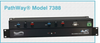
SPECIFICATIONS:
PORT CONNECTORS:
(3) RJ45 female connectors labeled A, B, and COMMON for Channel 1.
(3) RJ11 T1 female connectors labeled A, B, and COMMON for Channel 2.
FRONT PANEL CONTROL: (1) Manual pushbutton allows local switching.
DISPLAY: (2) Front panel LED's display switch position and power status.
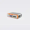
REMOTE CONTROL PORT: (1) DB9 (F) on rear panel accepts Contact Closure transition signals for Remote Control Operation.
POWER: UL approved 100VAC/240VAC, 50Hz/60Hz wall mount power module supplies 12 VDC, 500 mA to the unit. Has 2-prong, US, non-polarized plug.
DIMENSIONS: Rackmount configuration 19.0" W x 1.75" H x 8.16" D. (48.3 x 4.4 x 20.7 cm)
WEIGHT: Approximately 4.2 lbs. (1.9 kg)
DUAL CHANNEL A/B SWITCH APPLICATION w/CONTACT CLOSURE: CHANNEL 1: RJ45 CAT5e The drawing illustrates COMMON Device connected to the RJ45 Cat5e COMMON port with access to two other devices connected to the RJ45 Cat5e Port A and Port B, respectively. CHANNEL 2: RJ11 T1 The drawing also illustrates COMMON Device connected to the RJ11 T1 COMMON port with access to two other devices connected to the RJ11 T1 Port A and Port B, respectively. DB9 REMOTE PORT: The DB9 Remote port can be used to remotely control the switch via Contact Closure Signaling.
SPECIFICATIONS:
- PORT CONNECTORS:
- (3) RJ45 female connectors labeled A, B, and COMMON for Channel 1.
- (3) RJ11 T1 female connectors labeled A, B, and COMMON for Channel 2.
- FRONT PANEL CONTROL: (1) Manual pushbutton allows local switching.
- DISPLAY: (2) Front panel LED's display switch position and power status.
- REMOTE CONTROL PORT: (1) DB9 (F) on rear panel accepts Contact Closure transition signals for Remote Control Operation.
- POWER: UL approved 100VAC/240VAC, 50Hz/60Hz wall mount power module supplies 12 VDC, 500 mA to the unit. Has 2-prong, US, non-polarized plug.
- DIMENSIONS: Rackmount configuration 19.0" W x 1.75" H x 8.16" D.
(48.3 x 4.4 x 20.7 cm)
- WEIGHT: Approximately 4.2 lbs. (1.9 kg)
DUAL CHANNEL A/B SWITCH APPLICATION w/CONTACT CLOSURE:
CHANNEL 1: RJ45 CAT5e
The drawing illustrates COMMON Device connected to the RJ45 Cat5e COMMON port with access to two other devices connected to the RJ45 Cat5e Port A and Port B, respectively.
CHANNEL 2: RJ11 T1
The drawing also illustrates COMMON Device connected to the RJ11 T1 COMMON port with access to two other devices connected to the RJ11 T1 Port A and Port B, respectively.
DB9 REMOTE PORT: The DB9 Remote port can be used to remotely control the switch via Contact Closure Signaling.