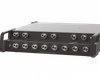
The ports are transparent to all data.
All 18 signal pins of the DVI-D Dual Link 24-pin connectors and all 9 Pins of the DB9 connectors are switched.
The DVI-D Dual Link signals are switched via solid state components using true DVI driver circuitry.
The signals of the DB9 connector are switched via solid state components.
In NORMAL mode, the A port is connected to C port and the B port is connected to the D port.
In CROSSOVER mode, the A port is connected to the D port, and the B port is connected to the C port.
Front panel LEDs display the current switch position and power status.
Manual operation accomplished by the use of a front panel pushbutton.
The DB9 REMOTE port provides access to remotely control the unit by dry contact open/closure logic.
Remote contact closure allows for lockout of the front panel pushbutton.
The switch will not continue to pass data in the event of power loss.
Switch powers up in last known position on power cycle.
Electro Standards Laboratories
Done
Datasheet
Description
The ports are transparent to all data.
All 18 signal pins of the DVI-D Dual Link 24-pin connectors and all 9 Pins of the DB9 connectors are switched.
The DVI-D Dual Link signals are switched via solid state components using true DVI driver circuitry.
The signals of the DB9 connector are switched via solid state components.
In NORMAL mode, the A port is connected to C port and the B port is connected to the D port.
In CROSSOVER mode, the A port is connected to the D port, and the B port is connected to the C port.
Front panel LEDs display the current switch position and power status.
Manual operation accomplished by the use of a front panel pushbutton.
The DB9 REMOTE port provides access to remotely control the unit by dry contact open/closure logic.
Remote contact closure allows for lockout of the front panel pushbutton.
The switch will not continue to pass data in the event of power loss.
Switch powers up in last known position on power cycle.
The ports are transparent to all data.
All 18 signal pins of the DVI-D Dual Link 24-pin connectors and all 9 Pins of the DB9 connectors are switched.
The DVI-D Dual Link signals are switched via solid state components using true DVI driver circuitry.
The signals of the DB9 connector are switched via solid state components.
In NORMAL mode, the A port is connected to C port and the B port is connected to the D port.
In CROSSOVER mode, the A port is connected to the D port, and the B port is connected to the C port.
Front panel LEDs display the current switch position and power status.
Manual operation accomplished by the use of a front panel pushbutton.
The DB9 REMOTE port provides access to remotely control the unit by dry contact open/closure logic.
Remote contact closure allows for lockout of the front panel pushbutton.
The switch will not continue to pass data in the event of power loss.
Switch powers up in last known position on power cycle.
The ports are transparent to all data.
All 18 signal pins of the DVI-D Dual Link 24-pin connectors and all 9 Pins of the DB9 connectors are switched.
The DVI-D Dual Link signals are switched via solid state components using true DVI driver circuitry.
The signals of the DB9 connector are switched via solid state components.
In NORMAL mode, the A port is connected to C port and the B port is connected to the D port.
In CROSSOVER mode, the A port is connected to the D port, and the B port is connected to the C port.
Front panel LEDs display the current switch position and power status.
Manual operation accomplished by the use of a front panel pushbutton.
The DB9 REMOTE port provides access to remotely control the unit by dry contact open/closure logic.
Remote contact closure allows for lockout of the front panel pushbutton.
The switch will not continue to pass data in the event of power loss.
Switch powers up in last known position on power cycle.