The Pro-Flo™ patented air distribution system incorporates three moving parts: The unbalanced air valve spool, the pilot spool, and the main shaft/diaphragm assembly. The air valve spool location directs pressurized air to one air chamber while exhausting the other. The pressurized air chamber causes the main shaft/diaphragm assembly to move outward discharging liquid on that side and pulling liquid in on the other side. When the shaft reaches the end of its stroke, the opposite inner piston actuates the pilot spool. The pilot spool location either pressurizes or exhausts the large end of the unbalanced air valve spool. When the large end is pressurized, the piston is forced up so that the air supply is routed through the air valve spool to the right side of the pump. When the large end is exhausted, the piston is forced down so that the air supply is routed through the air valve spool to the left side of the pump. Note: This valve design incorporates an unbalanced spool with the smaller end of the spool pressurized continuously.
The Pro-Flo™ patented air distribution system incorporates three moving parts: The unbalanced air valve spool, the pilot spool, and the main shaft/diaphragm assembly. The air valve spool location directs pressurized air to one air chamber while exhausting the other. The pressurized air chamber causes the main shaft/diaphragm assembly to move outward discharging liquid on that side and pulling liquid in on the other side. When the shaft reaches the end of its stroke, the opposite inner piston actuates the pilot spool. The pilot spool location either pressurizes or exhausts the large end of the unbalanced air valve spool. When the large end is pressurized, the piston is forced up so that the air supply is routed through the air valve spool to the right side of the pump. When the large end is exhausted, the piston is forced down so that the air supply is routed through the air valve spool to the left side of the pump. Note: This valve design incorporates an unbalanced spool with the smaller end of the spool pressurized continuously.
The Pro-Flo™ patented air distribution system incorporates three moving parts: The unbalanced air valve spool, the pilot spool, and the main shaft/diaphragm assembly. The air valve spool location directs pressurized air to one air chamber while exhausting the other. The pressurized air chamber causes the main shaft/diaphragm assembly to move outward discharging liquid on that side and pulling liquid in on the other side. When the shaft reaches the end of its stroke, the opposite inner piston actuates the pilot spool. The pilot spool location either pressurizes or exhausts the large end of the unbalanced air valve spool. When the large end is pressurized, the piston is forced up so that the air supply is routed through the air valve spool to the right side of the pump. When the large end is exhausted, the piston is forced down so that the air supply is routed through the air valve spool to the left side of the pump. Note: This valve design incorporates an unbalanced spool with the smaller end of the spool pressurized continuously.
| Pump Solutions Group | Pump Solutions Group | Pump Solutions Group | |
|---|---|---|---|
| Product Category | Liquid Handling Pumps | Liquid Handling Pumps | Liquid Handling Pumps |
| Product Number | P1 | P1 | P1 |
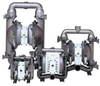
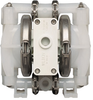
| Product Name | WILDEN Pro-Flo Metal Pump | WILDEN Pro-Flo Saniflo™ FDA | WILDEN Pro-Flo Plastic Pump |
| Pump Type | Self-Priming Pump; Submersible Pump | Self-Priming Pump; Submersible Pump | Piston Plunger Pump (optional feature); Self-Priming Pump; Submersible Pump |