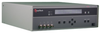
The 1920 is a 1 MHz LCR Meter from Quadtech. An LCR meter is a piece of electronic test equipment that measures inductance (L), capacitance (C), and resistance (R) of electronic components. The LCR meter accurately measures these elements on an electronic device, usually one subjected to an alternating current (AC) voltage source. The LCR meter measures the current through and voltage across the device under test.
Additional Features:
20 Measurement Parameters
Frequency Range 20 Hz to 1MHz
0.1% Basic Measurement Accuracy
Measurement Speeds Up to 40/sec
DC Resistance Measurements
Monitoring of DUT Voltage and Current
5 Digit Measurement Resolution
Programmable DC Bias Voltage, 0-2V
Constant Voltage (Voltage Leveling)
IEEE-488, RS-232 & Handler Interfaces, all Standard
Open/Short Zeroing & Cable Compensation
Load Correction
14 Pass/Fail Bins
Keypad Lockout
Specifications
Test Frequency:
Range: 20Hz to 1MHz, Continuous
Resolution: 1Hz from 20Hz to 1kHz,
4 digits >1kHz
Accuracy: ± (0.02% +0.02 Hz)
Measurement Speed:
Speed: Accuracy Setting
40 meas/sec: Low, No Display
25 meas/sec: Low
10 meas/sec: Medium
1 meas/sec: High
Ranging:
Automatic, Range Hold or user selectable
Trigger:
Internal (automatic)
External (via RS-232, IEEE-488.2 or Handler)
Manual
Source Impedance:
5ω, 25ω, 50ω, 100ω
AC Test Signal:
Voltage: 20mV-1.0V (open circuit), 5mV steps
DC Bias Voltage:
Internal: 0 to 2V in 1mV steps
Display:
LCD Display with backlight
Pass/Fail and status indicators
Results Formats:
Engineering or scientific format
%Deviation from nominal of primary parameter
Deviation from nominal of primary parameter
Pass/Fail
No Display Mode for maximum throughput
Sequencing:
Displays up to 6 sequential test results, primary and/or secondary
Standard Interfaces:
IEEE-488.2, RS-232, Handler
Measurement Delay:
Programmable from 0 to 1000ms in 1ms steps
Averaging:
Programmable from 1 to 1000
Median Value:
Averaged over last three measurements
Setup Storage:
30 Single Tests
10 Sequential (6 tests in each)
Other:
Constant Voltage Mode (voltage leveling)
Cable Compensation (1M, 2M, no cable)
Open/Short Zeroing
Distortion Check
Calibration:
Recommended interval 1 year
NIST traceable calibration
Built-in automatic calibration procedure
Usage & Cal Data:
Displays last calibration date, standard values used in calibration
Self Test:
Verifies critical instrument operation at power-up or when selected from menu
Test Terminals:
Front panel, four terminal (BNC)
Optional Test Fixtures Available
Mechanical:
Bench mount with tilt bail
Rack mount kit optional
Dimensions:
(w x h x d): 17 x 5.25 x 16 in (432 x 133 x 406 mm)
Environmental:
Meets MIL-28800E, Type 3, Class 5, Style E & F
Operating: 0° to +50°C
Humidity: < 75% for 11° to 30°C operating
Storage: -40° to +71° C
Power:
100-240 VAC 50/60 Hz, 100 W Max
Applications
Fast Production Testing of LCR Components and Materials
AC Impedance & DC Resistance Measurements
Component Characterization Over a Wide Frequency Range
Component Screening, Evaluation and Design
The 1920 is a high performance LCR Meter designed to perform fast, automated impedance measurements on a variety of electronic components and materials. The instrument has a basic accuracy specification of 0.1% for accurate test results over a wide frequency range, from 20 Hz to 1 MHz. Besides 15 impedance parameters the 1920 is also capable of measuring DC resistance as well as monitoring the voltage across or current through the device under test. The unit incorporates a distinctive sequence test mode, allowing up to 6 uniquely different tests to be performed quickly on a single start command. Additionally, the 1920 includes IEEE-488, RS-232, and handler interfaces, all standard.
20 Measurement Parameters Measure and display any two of 15 impedance parameters simultaneously, with a basic accuracy of 0.1%. Additionally, the 1920 can measure the DC resistance, or display the current through or voltage across a test device ensuring the operator of the real test conditions.
Wide Frequency Over 27,000 user programmable test frequencies to fully characterize devices over the range of 20 Hz to 1 MHz.
Automatic Test Sequencing For increased productivity and throughput the 1920 can perform up to six different tests in sequence with a single push of the start button. Each test can have different measurement parameters, test conditions and limits.
DC Bias Voltage The instruments internal DC bias voltage source, programmable from 0 to 2 V in 1 mV steps, allows capacitors to be tested under real DC bias conditions.
Setup Storage/Recall The test operator has the ability to store and recall, from internal memory, up to 30 single test setups and 10 sequential setups (six tests in sequence). The front panel can be locked out, with password protection, to ensure that procedures are run the same way every time.
Load Correction Substantially improves instrument accuracy by allowing the operator to specify the value of a known standard, measure it, and apply a correction to ongoing measurements.
Programmable Source Impedance The operator is able to set instrument source impedance at 5, 25, 50 or 100 ohms, an important feature when comparing measurements to those made on other testers. Measurement results can vary substantially based solely on the source impedance of the tester being used.
The 1920 is a 1 MHz LCR Meter from Quadtech. An LCR meter is a piece of electronic test equipment that measures inductance (L), capacitance (C), and resistance (R) of electronic components. The LCR meter accurately measures these elements on an electronic device, usually one subjected to an alternating current (AC) voltage source. The LCR meter measures the current through and voltage across the device under test.
Additional Features:
- 20 Measurement Parameters
- Frequency Range 20 Hz to 1MHz
- 0.1% Basic Measurement Accuracy
- Measurement Speeds Up to 40/sec
- DC Resistance Measurements
- Monitoring of DUT Voltage and Current
- 5 Digit Measurement Resolution
- Programmable DC Bias Voltage, 0-2V
- Constant Voltage (Voltage Leveling)
- IEEE-488, RS-232 & Handler Interfaces, all Standard
- Open/Short Zeroing & Cable Compensation
- Load Correction
- 14 Pass/Fail Bins
- Keypad Lockout
Specifications
Test Frequency:
- Range: 20Hz to 1MHz, Continuous
- Resolution: 1Hz from 20Hz to 1kHz,
- 4 digits >1kHz
- Accuracy: ± (0.02% +0.02 Hz)
Measurement Speed:
- Speed: Accuracy Setting
- 40 meas/sec: Low, No Display
- 25 meas/sec: Low
- 10 meas/sec: Medium
- 1 meas/sec: High
Ranging:
- Automatic, Range Hold or user selectable
Trigger:
- Internal (automatic)
- External (via RS-232, IEEE-488.2 or Handler)
- Manual
Source Impedance:
AC Test Signal:
- Voltage: 20mV-1.0V (open circuit), 5mV steps
DC Bias Voltage:
- Internal: 0 to 2V in 1mV steps
Display:
- LCD Display with backlight
- Pass/Fail and status indicators
Results Formats:
- Engineering or scientific format
- %Deviation from nominal of primary parameter
- Deviation from nominal of primary parameter
- Pass/Fail
- No Display Mode for maximum throughput
Sequencing:
- Displays up to 6 sequential test results, primary and/or secondary
Standard Interfaces:
- IEEE-488.2, RS-232, Handler
Measurement Delay:
- Programmable from 0 to 1000ms in 1ms steps
Averaging:
- Programmable from 1 to 1000
Median Value:
- Averaged over last three measurements
Setup Storage:
- 30 Single Tests
- 10 Sequential (6 tests in each)
Other:
- Constant Voltage Mode (voltage leveling)
- Cable Compensation (1M, 2M, no cable)
- Open/Short Zeroing
- Distortion Check
Calibration:
- Recommended interval 1 year
- NIST traceable calibration
- Built-in automatic calibration procedure
Usage & Cal Data:
- Displays last calibration date, standard values used in calibration
Self Test:
- Verifies critical instrument operation at power-up or when selected from menu
Test Terminals:
- Front panel, four terminal (BNC)
- Optional Test Fixtures Available
Mechanical:
- Bench mount with tilt bail
- Rack mount kit optional
Dimensions:
- (w x h x d): 17 x 5.25 x 16 in (432 x 133 x 406 mm)
Environmental:
- Meets MIL-28800E, Type 3, Class 5, Style E & F
- Operating: 0° to +50°C
- Humidity: < 75% for 11° to 30°C operating
- Storage: -40° to +71° C
Power:
- 100-240 VAC 50/60 Hz, 100 W Max
Applications
- Fast Production Testing of LCR Components and Materials
- AC Impedance & DC Resistance Measurements
- Component Characterization Over a Wide Frequency Range
- Component Screening, Evaluation and Design
The 1920 is a high performance LCR Meter designed to perform fast, automated impedance measurements on a variety of electronic components and materials. The instrument has a basic accuracy specification of 0.1% for accurate test results over a wide frequency range, from 20 Hz to 1 MHz. Besides 15 impedance parameters the 1920 is also capable of measuring DC resistance as well as monitoring the voltage across or current through the device under test. The unit incorporates a distinctive sequence test mode, allowing up to 6 uniquely different tests to be performed quickly on a single start command. Additionally, the 1920 includes IEEE-488, RS-232, and handler interfaces, all standard.
20 Measurement Parameters
Measure and display any two of 15 impedance parameters simultaneously, with a basic accuracy of 0.1%. Additionally, the 1920 can measure the DC resistance, or display the current through or voltage across a test device ensuring the operator of the real test conditions.
Wide Frequency
Over 27,000 user programmable test frequencies to fully characterize devices over the range of 20 Hz to 1 MHz.
Automatic Test Sequencing
For increased productivity and throughput the 1920 can perform up to six different tests in sequence with a single push of the start button. Each test can have different measurement parameters, test conditions and limits.
DC Bias Voltage
The instruments internal DC bias voltage source, programmable from 0 to 2 V in 1 mV steps, allows capacitors to be tested under real DC bias conditions.
Setup Storage/Recall
The test operator has the ability to store and recall, from internal memory, up to 30 single test setups and 10 sequential setups (six tests in sequence). The front panel can be locked out, with password protection, to ensure that procedures are run the same way every time.
Load Correction
Substantially improves instrument accuracy by allowing the operator to specify the value of a known standard, measure it, and apply a correction to ongoing measurements.
Programmable Source Impedance
The operator is able to set instrument source impedance at 5, 25, 50 or 100 ohms, an important feature when comparing measurements to those made on other testers. Measurement results can vary substantially based solely on the source impedance of the tester being used.