Features
16, 32, or 48 individually optically isolated solid-state outputs
Solid-state design permits high-speed switching and long-life expectancy
Wide 5V to 60 VDC output range
Optically isolated channel to channel and channel to ground
On-Card shields prevent accidental contact with user voltages
Outputs at zero volts at power turn-on and computer reset
Output connectors via on-card ribbon-cable headers
Lower cost per point than externally-racked solid-state relay modules
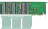
IDO-xx Series cards provide 16, 32, or 48 opto-isolated differential outputs and plug into expansion slots of IBM PC/XT/AT or compatible computers. Solid-state, P-Channel FET switches are used as the output elements and provide both greater reliability and much faster turn-on and turn-off time than is possible with electromechanical relays. User-supplied load voltages can be from 5V to 60V. Output connections are via 50-wire ribbon cables that mate with headers on the card. A strain relief bar where the cables exit the card assures that the cables will not interfere with adjacent cards. Standard cables are six feet long but alternate lengths are available. Model STA-50 Screw Terminal Accessory cards, one per each 16 bits, can be used to provide easy connection to your system.
The card uses six bytes of I/O Bus address; one byte for each eight bits of output. Outputs of a programmable array logic chip enable data bytes to be clocked into latches. Outputs of the latches, in turn, are connected via opto-couplers to the output P-channel FET drivers. The opto-couplers used are rated to at least 2000 VRMS and on-card isolation channel-to-channel and channel-to-computer exceeds 500 VRMS in optimal test environments (* see note). The P-Channel FET drivers are capable of 1 Ampere steady-state current, 2A pulse (Note: Current output may be limited by the cable to as little as 0.5A). Diodes are included across the load for inductive-spike protection.
*Note on Isolation: The Opto-isolators used are rated to at least 2000 VRMS. On-card isolation channel-to-channel and channel-to-ground is governed by factors such as cabling, spacing of pins, spacing between traces on the PCB, humidity, dust, and other environmental factors. This is a safety issue so a careful approach is required. For CE certification, isolation was specified at 60 VDC. The design intention was to eliminate the influence of common mode. Tolerance of higher isolation voltage can be obtained on request by applying a conformal coating to the board.
There are 48-bit, 32-bit, and 16-bit versions. The latter two models are de-populated versions of the 48-bit card.
Each bit of the IDO card is optically-isolated from the output driver which switches the supply voltage to the output pin. The negative connection is made on the return pin and each output is isolated from every other output.
When the opto-isolator is ON, the FET is activated by the Zener-diode-limited supply voltage. When the FET is ON, the full Supply voltage is available at the output pin. When the opto-isolator is deactivated, the FET opens and the output drops to the return line voltage level.
Note, because high voltages can be present, a protective cover is included and cables plugged into the headers on the card extend through this cover and exit the card through a cutout in the mounting bracket. (A strain-relief bar is also provided at that exit point.) If there is the possibility that some other card in your system will have sharp trimmed component leads that could pierce the cable(s), then you can use shielded "Zippertubing" (our part number ZTR-xx) to protect the cable and prevent possible short circuits.
Features
- 16, 32, or 48 individually optically isolated solid-state outputs
- Solid-state design permits high-speed switching and long-life expectancy
- Wide 5V to 60 VDC output range
- Optically isolated channel to channel and channel to ground
- On-Card shields prevent accidental contact with user voltages
- Outputs at zero volts at power turn-on and computer reset
- Output connectors via on-card ribbon-cable headers
- Lower cost per point than externally-racked solid-state relay modules
IDO-xx Series cards provide 16, 32, or 48 opto-isolated differential outputs and plug into expansion slots of IBM PC/XT/AT or compatible computers. Solid-state, P-Channel FET switches are used as the output elements and provide both greater reliability and much faster turn-on and turn-off time than is possible with electromechanical relays. User-supplied load voltages can be from 5V to 60V. Output connections are via 50-wire ribbon cables that mate with headers on the card. A strain relief bar where the cables exit the card assures that the cables will not interfere with adjacent cards. Standard cables are six feet long but alternate lengths are available. Model STA-50 Screw Terminal Accessory cards, one per each 16 bits, can be used to provide easy connection to your system.
The card uses six bytes of I/O Bus address; one byte for each eight bits of output. Outputs of a programmable array logic chip enable data bytes to be clocked into latches. Outputs of the latches, in turn, are connected via opto-couplers to the output P-channel FET drivers. The opto-couplers used are rated to at least 2000 VRMS and on-card isolation channel-to-channel and channel-to-computer exceeds 500 VRMS in optimal test environments (* see note). The P-Channel FET drivers are capable of 1 Ampere steady-state current, 2A pulse (Note: Current output may be limited by the cable to as little as 0.5A). Diodes are included across the load for inductive-spike protection.
*Note on Isolation: The Opto-isolators used are rated to at least 2000 VRMS. On-card isolation channel-to-channel and channel-to-ground is governed by factors such as cabling, spacing of pins, spacing between traces on the PCB, humidity, dust, and other environmental factors. This is a safety issue so a careful approach is required. For CE certification, isolation was specified at 60 VDC. The design intention was to eliminate the influence of common mode. Tolerance of higher isolation voltage can be obtained on request by applying a conformal coating to the board.
There are 48-bit, 32-bit, and 16-bit versions. The latter two models are de-populated versions of the 48-bit card.
Each bit of the IDO card is optically-isolated from the output driver which switches the supply voltage to the output pin. The negative connection is made on the return pin and each output is isolated from every other output.
When the opto-isolator is ON, the FET is activated by the Zener-diode-limited supply voltage. When the FET is ON, the full Supply voltage is available at the output pin. When the opto-isolator is deactivated, the FET opens and the output drops to the return line voltage level.
Note, because high voltages can be present, a protective cover is included and cables plugged into the headers on the card extend through this cover and exit the card through a cutout in the mounting bracket. (A strain-relief bar is also provided at that exit point.) If there is the possibility that some other card in your system will have sharp trimmed component leads that could pierce the cable(s), then you can use shielded "Zippertubing" (our part number ZTR-xx) to protect the cable and prevent possible short circuits.