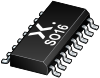

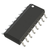
The 74HC191 is an asynchronously presettable 4-bit binary up/down counter. It contains four master/slave flip-flops with internal gating and steering logic to provide asynchronous preset and synchronous count-up and count-down operation. Asynchronous parallel load capability permits the counter to be preset to any desired value. Information present on the parallel data inputs (D0 to D3) is loaded into the counter and appears on the outputs when the parallel load (PL) input is LOW. This operation overrides the counting function. Counting is inhibited by a HIGH level on the count enable (CE) input. When CEis LOW internal state changes are initiated synchronously by the LOW-to-HIGH transition of the clock input. The up/down (U/D) input signal determines the direction of counting as indicated in the function table. The CEinput may go LOW when the clock is in either state, however, the LOW-to-HIGH CEtransition must occur only when the clock is HIGH. Also, the U/D input should be changed only when either CEor CP is HIGH. Overflow/underflow indications are provided by two types of outputs, the terminal count (TC) and ripple clock (RC). The TC output is normally LOW and goes HIGH when a circuit reaches zero in the count-down mode or reaches '15' in the count-up-mode. The TC output will remain HIGH until a state change occurs, either by counting or presetting, or until U/D is changed. Do not use the TC output as a clock signal because it is subject to decoding spikes. The TC signal is used internally to enable the RCoutput. When TC is HIGH and CEis LOW, the RCoutput follows the clock pulse (CP). This feature simplifies the design of multistage counters as shown in Figure 1 and Figure 2. In Figure 1, each RCoutput is used as the clock input to the next higher stage. It is only necessary to inhibit the first stage to prevent counting in all stages, since a HIGH on CEinhibits the RCoutput pulse. The timing skew between state changes in the first and last stages is represented by the cumulative delay of the clock as it ripples through the preceding stages. This can be a disadvantage of this configuration in some applications. Figure 2 shows a method of causing state changes to occur simultaneously in all stages. The RCoutputs propagate the carry/borrow signals in ripple fashion and all clock inputs are driven in parallel. In this configuration the duration of the clock LOW state must be long enough to allow the negative-going edge of the carry/borrow signal to ripple through to the last stage before the clock goes HIGH. Since the RCoutput of any package goes HIGH shortly after its CP input goes HIGH there is no such restriction on the HIGH-state duration of the clock. In Figure 3, the configuration shown avoids ripple delays and their associated restrictions. Combining the TC signals from all the preceding stages forms the CEinput for a given stage. An enable must be included in each carry gate in order to inhibit counting. The TC output of a given stage it not affected by its own CEsignal therefore the simple inhibit scheme of Figure 1 and Figure 2 does not apply. Inputs include clamp diodes. This enables the use of current limiting resistors to interface inputs to voltages in excess of VCC.
Features and benefits
Counter IC Binary Counter 1 Element 4 Bit Positive Edge 16-SO
IC BINARY COUNTER 4-BIT 16SO
IC BINARY COUNTER 4-BIT 16SO
IC 4BIT BINAR UP/DN COUNT 16SOIC
Counter IC Binary Counter 1 Element 4 Bit Positive Edge 16-SO
IC BINARY COUNTER 4-BIT 16SO
| Nexperia B.V. | DigiKey | Lingto Electronic Limited | Quarktwin Technology Ltd. | Shenzhen Shengyu Electronics Technology Limited | |
|---|---|---|---|---|---|
| Product Category | Logic Counters | Logic Counters | Logic Counters | Logic Counters | Logic Counters |
| Product Number | 74HC191D,653 | 1727-74HC191D,653TR-ND | 74HC191D,653 | 74HC191D,653 | 74HC191D,653 |
| Product Name | Presettable synchronous 4-bit binary up/down counter | Counters, Dividers | Logic - Counters, Dividers | Counters, Dividers | Integrated Circuits (ICs) - Logic - Counters, Dividers |
| Features | ESD Protection | ||||
| Counter Category | Synchronous; Asynchronous | Synchronous; Asynchronous | Synchronous | ||
| Counter Direction | Bidirectional | Bidirectional | UP; DOWN | ||
| Supply Voltage | +7.0 | 2 V ~ 6 V |




