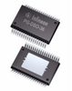
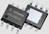
The TLE7368-2E device is a multifunctional power supply circuit especially designed for Automotive powertrain systems using a standard 12 V battery.
The device is intended to supply and monitor next generation 32-bit microcontroller families (13 μm lithography) where voltage levels such as 5 V, 3.3 V or 1.2 V are required. The regulator follows the concept of its predecessor TLE6368, where the output of a pre-regulator feeds the inputs of the micro’s linear supplies. In detail, the TLE7368 cascades a Buck converter with linear regulators and voltage followers to achieve lowest power dissipation. This configuration allows to power the application even at high ambient temperatures. The step-down converter delivers a pre-regulated voltage of 5.5 V with a minimum peak current capability of 2.5 A. Supplied by this step down converter two low drop linear post-regulators offer 5 V and 3.3 V (2.6 V) with high accuracy. The current capability of the regulators is 800 mA and 700 mA. The 3.3 V (2.6 V) linear regulator does have its own input allowing to insert a dropper from the Buck output to reduce the on chip power dissipation if necessary. For the same reason, reduction of on chip power dissipation, the core supply (1.5 V, 1.2 V or 1.3 V) follows the concept of integrated control circuit with external power stage. Implementing the on board and microcontroller supplies in this way described, allows operation even at high ambient temperatures. The regulator system contains the so called power sequencing function which provides a controlled power up sequence of the three output voltages.In addition to the main regulators the inputs of two voltage trackers are connected to the 5.5 V Buck converter output voltage. Their protected outputs follow the main 5 V linear regulator with high accuracy and are able to drive loads of 50 mA and 105 mA. To monitor the output voltage levels of each of the linear regulators two independent undervoltage detection circuits are available. They can be used to implement the reset or an interrupt function.For energy saving reasons, e.g. while the motor is turned off, the TLE7368 offers a stand-by mode. The standby mode can be enabled and disabled either by battery or the microcontroller. In this stand-by mode just the standby regulator remains active and the current drawn from battery is reduced to a minimum for extended battery lifetime. A selection pin allows to configure the output voltages of the stand-by regulator to the application’s needs. The input of the stand-by regulator is separated from the high power input of the pre-/post-regulator system. The TLE7368 is based on Infineon’s Power technology SPT™ which allows bipolar, CMOS and power DMOS circuitry to be integrated on the same monolithic chip/circuitry.
Summary of Features
High efficient next generation microcontroller power supply system
Wide battery input voltage range < 4.5 V up to 45 V
Operating temperature range Tj = -40 °C to +150 °C
Pre-regulator for low all over power loss: Integrated current mode Buck converter 5.5 V/2.5 A
Post-regulators, e.g. for system and controller I/O supply: LDO1: 5V ±2%, 800 mA current limit ,LDO2: 3.3 V ±2% or 2.6V ±2% (selectable output), 700 mA current limit
Integrated linear regulator control circuit to supply controller cores: LDO3 control for an external NPN power stage: 1.2V ±2%
Post-regulators for off board supply: 2 Tracking regulators following the main 5 V, 105 mA and 50 mA
Stand-by regulator with lowest current consumption: Linear voltage regulator as stand-by supply for e.g. memory circuits Hardware selectable output voltages as 1.0 V or 2.6 V, 30 mA, Independent battery input, separated from Buck regulator input
Hardware controlled on/off logic
Undervoltage detection: Undervoltage reset circuits with adjustable reset delay time at power up, Undervoltage monitoring circuit on stand-by supply
Window watchdog circuit
Overcurrent protection on all regulators
Power sequencing on controller supplies
Overtemperature shutdown
Packages: Low Rthja Power-P-DSO-36; small exposed pad PG-DSO-36
PG-DSO-36 only: Green Product (RoHS compliant)
AEC Qualified
Benefits
High efficiency for complex supply systems
Low current consumption in stand-by
Easy realization of multiple supply rail systems
Monitoring and control of µC by reset generator and window-watchdog
Thermal enhanced exposed-pad package for wide temperature range
Potential Applications
Powertrain: Transmission, EMS
Safety: EPS
Family Overview
For different output voltage and package variants please click here.
Applications
Active suspension control
Automatic transmission hydraulic system
Electric vehicle (EV) drivetrain system
EV traction inverter
On-board charging (OBC) for electric vehicles
Designers who used this product also designed with
TLE8242-2L | Constant current control IC for transmission
FS05MR12A6MA1B | Silicon Carbide CoolSiC™ MOSFET Modules
TLE42764GV | OPTIREG™ linear voltage regulators (LDO)
FS03MR12A6MA1B | Silicon Carbide CoolSiC™ MOSFET Modules
SPD09P06PL G | P-Channel Power MOSFET
IPD25N06S2-40 | Automotive MOSFET
IPW65R048CFDA | Automotive MOSFET
IPW65R080CFDA | Automotive MOSFET
SAK-TC375TP-96F300W AA | AURIX™ Family – TC37xTP
IPD90P03P4-04 | Automotive MOSFET
IPW65R150CFDA | Automotive MOSFET
SAK-TC264D-40F200N BC | AURIX™ Family – TC26xD
IPG20N06S2L-65 | Automotive MOSFET
BTS5200-4EKA | PROFET™ + 12V | automotive smart high-side switch
TLE8110ED | FLEX
TLE4267G | OPTIREG™ linear voltage regulators (LDO)
TLE8242-2L | Constant current control IC for transmission
FS05MR12A6MA1B | Silicon Carbide CoolSiC™ MOSFET Modules
TLE42764GV | OPTIREG™ linear voltage regulators (LDO)
FS03MR12A6MA1B | Silicon Carbide CoolSiC™ MOSFET Modules
SPD09P06PL G | P-Channel Power MOSFET
IPD25N06S2-40 | Automotive MOSFET
IPW65R048CFDA | Automotive MOSFET
IPW65R080CFDA | Automotive MOSFET
1 2 3 4
Ask the Power Management Ics Community
Infineon Developer Community is available 24x7 for you to connect and network with engineers across the globe. Get help from Infineon support engineers, and expert members to solve your design challenges anytime, from anywhere, in any topic, and in your preferred language.
Ask the Community
The TLE7368-2E device is a multifunctional power supply circuit especially designed for Automotive powertrain systems using a standard 12 V battery.
The device is intended to supply and monitor next generation 32-bit microcontroller families (13 μm lithography) where voltage levels such as 5 V, 3.3 V or 1.2 V are required. The regulator follows the concept of its predecessor TLE6368, where the output of a pre-regulator feeds the inputs of the micro’s linear supplies. In detail, the TLE7368 cascades a Buck converter with linear regulators and voltage followers to achieve lowest power dissipation. This configuration allows to power the application even at high ambient temperatures. The step-down converter delivers a pre-regulated voltage of 5.5 V with a minimum peak current capability of 2.5 A. Supplied by this step down converter two low drop linear post-regulators offer 5 V and 3.3 V (2.6 V) with high accuracy. The current capability of the regulators is 800 mA and 700 mA. The 3.3 V (2.6 V) linear regulator does have its own input allowing to insert a dropper from the Buck output to reduce the on chip power dissipation if necessary. For the same reason, reduction of on chip power dissipation, the core supply (1.5 V, 1.2 V or 1.3 V) follows the concept of integrated control circuit with external power stage. Implementing the on board and microcontroller supplies in this way described, allows operation even at high ambient temperatures. The regulator system contains the so called power sequencing function which provides a controlled power up sequence of the three output voltages.In addition to the main regulators the inputs of two voltage trackers are connected to the 5.5 V Buck converter output voltage. Their protected outputs follow the main 5 V linear regulator with high accuracy and are able to drive loads of 50 mA and 105 mA. To monitor the output voltage levels of each of the linear regulators two independent undervoltage detection circuits are available. They can be used to implement the reset or an interrupt function.For energy saving reasons, e.g. while the motor is turned off, the TLE7368 offers a stand-by mode. The standby mode can be enabled and disabled either by battery or the microcontroller. In this stand-by mode just the standby regulator remains active and the current drawn from battery is reduced to a minimum for extended battery lifetime. A selection pin allows to configure the output voltages of the stand-by regulator to the application’s needs. The input of the stand-by regulator is separated from the high power input of the pre-/post-regulator system. The TLE7368 is based on Infineon’s Power technology SPT™ which allows bipolar, CMOS and power DMOS circuitry to be integrated on the same monolithic chip/circuitry.
Summary of Features
- High efficient next generation microcontroller power supply system
- Wide battery input voltage range < 4.5 V up to 45 V
- Operating temperature range Tj = -40 °C to +150 °C
- Pre-regulator for low all over power loss: Integrated current mode Buck converter 5.5 V/2.5 A
- Post-regulators, e.g. for system and controller I/O supply: LDO1: 5V ±2%, 800 mA current limit ,LDO2: 3.3 V ±2% or 2.6V ±2% (selectable output), 700 mA current limit
- Integrated linear regulator control circuit to supply controller cores: LDO3 control for an external NPN power stage: 1.2V ±2%
- Post-regulators for off board supply: 2 Tracking regulators following the main 5 V, 105 mA and 50 mA
- Stand-by regulator with lowest current consumption: Linear voltage regulator as stand-by supply for e.g. memory circuits Hardware selectable output voltages as 1.0 V or 2.6 V, 30 mA, Independent battery input, separated from Buck regulator input
- Hardware controlled on/off logic
- Undervoltage detection: Undervoltage reset circuits with adjustable reset delay time at power up, Undervoltage monitoring circuit on stand-by supply
- Window watchdog circuit
- Overcurrent protection on all regulators
- Power sequencing on controller supplies
- Overtemperature shutdown
- Packages: Low Rthja Power-P-DSO-36; small exposed pad PG-DSO-36
- PG-DSO-36 only: Green Product (RoHS compliant)
- AEC Qualified
Benefits
- High efficiency for complex supply systems
- Low current consumption in stand-by
- Easy realization of multiple supply rail systems
- Monitoring and control of µC by reset generator and window-watchdog
- Thermal enhanced exposed-pad package for wide temperature range
Potential Applications
- Powertrain: Transmission, EMS
- Safety: EPS
Family Overview
For different output voltage and package variants please click here.
Applications
- Active suspension control
- Automatic transmission hydraulic system
- Electric vehicle (EV) drivetrain system
- EV traction inverter
- On-board charging (OBC) for electric vehicles
Designers who used this product also designed with
- TLE8242-2L |
Constant current control IC for transmission
- FS05MR12A6MA1B |
Silicon Carbide CoolSiC™ MOSFET Modules
- TLE42764GV |
OPTIREG™ linear voltage regulators (LDO)
- FS03MR12A6MA1B |
Silicon Carbide CoolSiC™ MOSFET Modules
- SPD09P06PL G |
P-Channel Power MOSFET
- IPD25N06S2-40 |
Automotive MOSFET
- IPW65R048CFDA |
Automotive MOSFET
- IPW65R080CFDA |
Automotive MOSFET
- SAK-TC375TP-96F300W AA |
AURIX™ Family – TC37xTP
- IPD90P03P4-04 |
Automotive MOSFET
- IPW65R150CFDA |
Automotive MOSFET
- SAK-TC264D-40F200N BC |
AURIX™ Family – TC26xD
- IPG20N06S2L-65 |
Automotive MOSFET
- BTS5200-4EKA |
PROFET™ + 12V | automotive smart high-side switch
- TLE8110ED |
FLEX
- TLE4267G |
OPTIREG™ linear voltage regulators (LDO)
- TLE8242-2L |
Constant current control IC for transmission
- FS05MR12A6MA1B |
Silicon Carbide CoolSiC™ MOSFET Modules
- TLE42764GV |
OPTIREG™ linear voltage regulators (LDO)
- FS03MR12A6MA1B |
Silicon Carbide CoolSiC™ MOSFET Modules
- SPD09P06PL G |
P-Channel Power MOSFET
- IPD25N06S2-40 |
Automotive MOSFET
- IPW65R048CFDA |
Automotive MOSFET
- IPW65R080CFDA |
Automotive MOSFET
1
2
3
4
Ask the Power Management Ics Community
Infineon Developer Community is available 24x7 for you to connect and network with engineers across the globe. Get help from Infineon support engineers, and expert members to solve your design challenges anytime, from anywhere, in any topic, and in your preferred language.
Ask the Community