Waterman Industries, Inc. C-20 Canal Gates

Description
The canal gates shall be Waterman Model C-20 or approved equal. General The gates shall be self-contained with yoke and bench stand operators; self-contained with either non-rising stem extension (NRE) or rising stem extensions (RSE); or gates with minimum height frames and separate stem guides and operators, in accordance with requirements of these specifications. Specific gate design and configuration shall be noted in gate schedule or as shown on plans. Frame and Cover (Slide) The frame and cover (slide) shall be cast iron with machined seating faces. The frame shall be flatback or spigotback special mounting configuration as specified. Grooves shall be cast on the vertical sides of the cover to match guide angles. The cover shall be of domed design to withstand a maximum seating head of 20 feet or unseating head of 10 feet. The guide rails and head rails shall be minimum 1/4-inch thick steel, designed and built to withstand the total thrust of the gate slide due to water pressure and wedge action. There shall be one adjustable cast iron wedge per side, located on the horizontal centerline of the gate. A heavy cast iron arch shall be provided and bolted to the slide. The ends of the arch shall contain integrally cast wedges, which shall wedge in beneath the other half of the wedge system, attached to the guide rails with two bolts. The wedges shall have smooth bearing surfaces and shall be adjustable to insure effective contact between gate seating surfaces. Stem The stem shall be cold finished steel of suitable length and ample strength for the intended service. The stem diameter shall be capable of withstanding twice the rated out put of the operator at 40 pound pull, and shall be supported such that the L/r ratio for the unsupported part of the stem shall not exceed 200. When rising stem extension is used, the stem extension shall be supported such that a rigid installation shall be provided. Stem guides shall be spaced such that the L/r ratio of the stem does not exceed 200. Operators Manually operated lifting mechanisms shall be indicated on the plan drawings or in the gate schedule. Handwheel type lifts shall have threaded bronze lift nut to match stem. Threads shall be machine cut, acme type. An arrow shall be cast on the handwheel to indicate the direction of rotation to open the gate. A maximum effort of 40 pounds shall be required to operate the gate after it is unseated, based on the maximum specified operating head. Material Frame, Cover (slide), Handwheel - Cast Iron - ASTM A-126, Class B. Rails and Yoke - Painted Structural Steel - ASTM A-36. Stem - Leaded cold rolled steel - ASTM A-108, Gr. 12L14. Lift Nut - Bronze - ASTM B-584, Alloy 836 or 865. Assembly Hardware and Fasteners - Galvanized per ASTM A-153. Paint - Manufacturer's Standard.
Description
The canal gates shall be Waterman Model C-20 or approved equal. General The gates shall be self-contained with yoke and bench stand operators; self-contained with either non-rising stem extension (NRE) or rising stem extensions (RSE); or gates with minimum height frames and separate stem guides and operators, in accordance with requirements of these specifications. Specific gate design and configuration shall be noted in gate schedule or as shown on plans. Frame and Cover (Slide) The frame and cover (slide) shall be cast iron with machined seating faces. The frame shall be flatback or spigotback special mounting configuration as specified. Grooves shall be cast on the vertical sides of the cover to match guide angles. The cover shall be of domed design to withstand a maximum seating head of 20 feet or unseating head of 10 feet. The guide rails and head rails shall be minimum 1/4-inch thick steel, designed and built to withstand the total thrust of the gate slide due to water pressure and wedge action. There shall be one adjustable cast iron wedge per side, located on the horizontal centerline of the gate. A heavy cast iron arch shall be provided and bolted to the slide. The ends of the arch shall contain integrally cast wedges, which shall wedge in beneath the other half of the wedge system, attached to the guide rails with two bolts. The wedges shall have smooth bearing surfaces and shall be adjustable to insure effective contact between gate seating surfaces. Stem The stem shall be cold finished steel of suitable length and ample strength for the intended service. The stem diameter shall be capable of withstanding twice the rated out put of the operator at 40 pound pull, and shall be supported such that the L/r ratio for the unsupported part of the stem shall not exceed 200. When rising stem extension is used, the stem extension shall be supported such that a rigid installation shall be provided. Stem guides shall be spaced such that the L/r ratio of the stem does not exceed 200. Operators Manually operated lifting mechanisms shall be indicated on the plan drawings or in the gate schedule. Handwheel type lifts shall have threaded bronze lift nut to match stem. Threads shall be machine cut, acme type. An arrow shall be cast on the handwheel to indicate the direction of rotation to open the gate. A maximum effort of 40 pounds shall be required to operate the gate after it is unseated, based on the maximum specified operating head. Material Frame, Cover (slide), Handwheel - Cast Iron - ASTM A-126, Class B. Rails and Yoke - Painted Structural Steel - ASTM A-36. Stem - Leaded cold rolled steel - ASTM A-108, Gr. 12L14. Lift Nut - Bronze - ASTM B-584, Alloy 836 or 865. Assembly Hardware and Fasteners - Galvanized per ASTM A-153. Paint - Manufacturer's Standard.

Suppliers

Company
Product
Description
Supplier Links
 - C-20 Canal Gates - Waterman Industries, Inc.
Exeter, CA, USA
C-20 Canal Gates
C-20 Canal Gates
The canal gates shall be Waterman Model C-20 or approved equal. General The gates shall be self-contained with yoke and bench stand operators; self-contained with either non-rising stem extension (NRE) or rising stem extensions (RSE); or gates with minimum height frames and separate stem guides and operators, in accordance with requirements of these specifications. Specific gate design and configuration shall be noted in gate schedule or as shown on plans. Frame and Cover (Slide) The frame and cover (slide) shall be cast iron with machined seating faces. The frame shall be flatback or spigotback special mounting configuration as specified. Grooves shall be cast on the vertical sides of the cover to match guide angles. The cover shall be of domed design to withstand a maximum seating head of 20 feet or unseating head of 10 feet. The guide rails and head rails shall be minimum 1/4-inch thick steel, designed and built to withstand the total thrust of the gate slide due to water pressure and wedge action. There shall be one adjustable cast iron wedge per side, located on the horizontal centerline of the gate. A heavy cast iron arch shall be provided and bolted to the slide. The ends of the arch shall contain integrally cast wedges, which shall wedge in beneath the other half of the wedge system, attached to the guide rails with two bolts. The wedges shall have smooth bearing surfaces and shall be adjustable to insure effective contact between gate seating surfaces. Stem The stem shall be cold finished steel of suitable length and ample strength for the intended service. The stem diameter shall be capable of withstanding twice the rated out put of the operator at 40 pound pull, and shall be supported such that the L/r ratio for the unsupported part of the stem shall not exceed 200. When rising stem extension is used, the stem extension shall be supported such that a rigid installation shall be provided. Stem guides shall be spaced such that the L/r ratio of the stem does not exceed 200. Operators Manually operated lifting mechanisms shall be indicated on the plan drawings or in the gate schedule. Handwheel type lifts shall have threaded bronze lift nut to match stem. Threads shall be machine cut, acme type. An arrow shall be cast on the handwheel to indicate the direction of rotation to open the gate. A maximum effort of 40 pounds shall be required to operate the gate after it is unseated, based on the maximum specified operating head. Material Frame, Cover (slide), Handwheel - Cast Iron - ASTM A-126, Class B. Rails and Yoke - Painted Structural Steel - ASTM A-36. Stem - Leaded cold rolled steel - ASTM A-108, Gr. 12L14. Lift Nut - Bronze - ASTM B-584, Alloy 836 or 865. Assembly Hardware and Fasteners - Galvanized per ASTM A-153. Paint - Manufacturer's Standard.

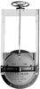
The canal gates shall be Waterman Model C-20 or approved equal.

General
The gates shall be self-contained with yoke and bench stand operators; self-contained with either non-rising stem extension (NRE) or rising stem extensions (RSE); or gates with minimum height frames and separate stem guides and operators, in accordance with requirements of these specifications. Specific gate design and configuration shall be noted in gate schedule or as shown on plans.

Frame and Cover (Slide)
The frame and cover (slide) shall be cast iron with machined seating faces. The frame shall be flatback or spigotback special mounting configuration as specified. Grooves shall be cast on the vertical sides of the cover to match guide angles. The cover shall be of domed design to withstand a maximum seating head of 20 feet or unseating head of 10 feet. The guide rails and head rails shall be minimum 1/4-inch thick steel, designed and built to withstand the total thrust of the gate slide due to water pressure and wedge action. There shall be one adjustable cast iron wedge per side, located on the horizontal centerline of the gate. A heavy cast iron arch shall be provided and bolted to the slide. The ends of the arch shall contain integrally cast wedges, which shall wedge in beneath the other half of the wedge system, attached to the guide rails with two bolts. The wedges shall have smooth bearing surfaces and shall be adjustable to insure effective contact between gate seating surfaces.

Stem
The stem shall be cold finished steel of suitable length and ample strength for the intended service. The stem diameter shall be capable of withstanding twice the rated out put of the operator at 40 pound pull, and shall be supported such that the L/r ratio for the unsupported part of the stem shall not exceed 200. When rising stem extension is used, the stem extension shall be supported such that a rigid installation shall be provided. Stem guides shall be spaced such that the L/r ratio of the stem does not exceed 200.

Operators
Manually operated lifting mechanisms shall be indicated on the plan drawings or in the gate schedule. Handwheel type lifts shall have threaded bronze lift nut to match stem. Threads shall be machine cut, acme type. An arrow shall be cast on the handwheel to indicate the direction of rotation to open the gate. A maximum effort of 40 pounds shall be required to operate the gate after it is unseated, based on the maximum specified operating head.

Material
Frame, Cover (slide), Handwheel - Cast Iron - ASTM A-126, Class B. Rails and Yoke - Painted Structural Steel - ASTM A-36. Stem - Leaded cold rolled steel - ASTM A-108, Gr. 12L14. Lift Nut - Bronze - ASTM B-584, Alloy 836 or 865. Assembly Hardware and Fasteners - Galvanized per ASTM A-153. Paint - Manufacturer's Standard. </…

Technical Specifications

  Waterman Industries, Inc.
Product Category Industrial Valves
Product Number C-20 Canal Gates
Valve Type Gate
Unlock Full Specs
to access all available technical data

Similar Products

HVXM Large Body PTFE Valve - 36782 - Hamilton Company
Specs
Valve Type Directional; Plug
Primary Material Aluminum; PTFE; CTFE
Media Chemical
View Details
Ball Valves, BV -  - Rotork plc
Specs
Valve Type Ball
Maximum Pressure 10000.00 psi (7038 m H2O)
Flow (Cv) 19.00
View Details
 - Compressed Air Flow Regulating Butterfly Valve - DHS Series - Kaeser Compressors, Inc.
Specs
Valve Type Butterfly
Media Air; Compressed Air
Valve Size 2.00 to 8.00 inch (50.80 to 203.20 mm)
View Details