ValueTronics International, Inc. Arbitrary Waveform Generator SG-100/A

Description
The SG-100/A is a 21.5 GHz arbitrary waveform generator from Telulex. An arbitrary waveform generator (AWG) is a type of electronic test equipment people use to generate repetitive or single-shot electrical waveforms. Single-shot waveforms require a triggering source, either internal or external, while repetitive waveforms do not. Inject the signal the waveform generator creates into a device for analysis during testing, finding problems with the device, or confirming proper operation. Additional Features: Sine, Square, Ramp, Triangle, Random AM, FM, PM, FSK ARB with no phase jitter nor missed points Word and Data Fenerator Phase Lock between units Burst-continuous or triggered Voltage and Power Measurement SSB, BPSK-Internal & External Modulation DTMF-Generate & Detect Main Output Frequency: DC to 21.5000000 MHz, 0.01 Hz steps Level: 2 mV p-p to 5.000 V p-p, 1 mV steps (into 50 ½) or -50.0 dBm to +18.0 dBm, 0.1 dBm steps (into 50 ½) Level Accuracy: ± 1% Flatness: ± 0.2 dB (DC-20 MHz) DC offset: 0 V to ± 4.0 V, 1 mV steps (into 50 ½) Output impedance: 50 ½ Freq. Accuracy: ± 10 ppm (± 5 ppm optional) Phase Noise: < -55 dBc in a 30 kHz band Spectral Purity: DC to 100 kHz: > -50 dBc 100 kHz to 1 MHz: > -45 dBc 1 MHz to 12 MHz: > -40 dBc 12 MHz to 20 MHz: > -35 dBc Ext. Trigger/Gating/FSK/B PSK Input Input impedance: 80 K½; Max. input level: ± 10 V; Max. gating freq: 3 MHz SYNC Output Amplitude: 0 V to +5 V (TTL/CMOS compatible) Rise/Fall Time: Rise: < 8 ns; Fall: < 3 ns Output Current: ± 24 mA External Modulation Input Maximum full scale input: ± 5 V (10 V p-p) Input Impedance: 30 K½ Ext. Arb Clock Input Input level: TLL/CMOS Max. clock freq.: 40 MHz Connectors Front Panel: Sync Out; Sig Out Rear Panel: Ext Modulation, Power/Volts Meas Input; Ext Trigger, Gating, FSK/BPSK Input; Ext Ref, Ext Arb Clock; Ext Arb Sync In/Out RS232 port Asynchronous, no parity, 1 start bit, 1 stop bit Baud rate: Adjustable, 300 bps to 115,200 bps Remote operation from a terminal or host computer General Power: 100-240 VAC 47-63 Hz, 30 W, 3 prong IEC connector Display: 2 line by 40 character, LCD, backlit Weight: Approx. 3.5 lbs. Dimensions: 5.1” x 9.3” x 10.2” (H x W x L) Operating Temperature: 0 to 40 deg. C ambient Other Modes and Applications Information The carrier frequency for all modulation modes is 0 Hz to 21.500000 MHz, 0.01 Hz steps All internal modulation frequencies are synthesized and are accurate to 0.01% Basic Sinewave (CW) Mode Output frequency: 0 Hz to 21.500 MHz, 0.01 Hz steps Frequency Modulation (FM) Mode Int. modulation freq: 0 Hz to 10 kHz, 1 Hz steps Ext. modulation freq: DC to 35 kHz Peak frequency deviation: 0 Hz to ± 5.0 MHz, 1 Hz steps Phase Modulation (PM) Mode Int. modulation freq: 0 Hz to 10 kHz, 1 Hz steps Ext. modulation freq: DC to 35 kHz Peak phase deviation: 0 to ± 180 deg., 1 deg. steps Sweep Mode Start/Stop freq: 0 Hz to 21.500 MHz, 0.01 Hz steps Linear or Log sweep. Up or Down sweep direction Free Run or Triggered sweep (Int/Ext) Sweep time: 1 ms to 60 s 1 ms steps Burst Mode Continuous or triggered from front panel, RS232 or Ext Trig Duration: 1 ms to 99.999 s, 1 ms steps Delay: 0 ms to 99.999 s, 1 ms steps Dual Tone Multi Frequency (DTMF) Generate Mode Dialing digits generated: 0 to 9, #, *, A, B, C, D Duration: 1 ms to 10.000 s, 1 ms steps Delay: 0 ms to 10.000 s, 1 ms steps Custom Dual Tone Generate Mode Tone 1, Tone 2 Frequency: DC to 10.000 kHz, 1 Hz steps Phase Offset: 0 deg. to 359 deg., 1 deg. steps Output ON time: Cont. or 1 ms to 10.000 s, 1 ms steps Output OFF time: 0 ms to 10.000 s, 1 ms steps Voltage Controlled Oscillator (VCO) Mode Endpoint Frequencies: 0 Hz to 21.5000000 MHz in 0.01 Hz steps Control input range: ± 5.0 V Control signal bandwidth: DC to 35 kHz Amplitude Modulation (AM) Mode Int. modulation freq: 0 Hz to 10 kHz, 1 Hz steps Ext. modulation freq: DC to 35 kHz Percentage modulation: Variable 0% to 100%, 1% steps Single Sideband (SSB) Mode Int. modulation freq: 0 Hz to 5 MHz, 1 Hz steps Ext. modulation freq: DC to 8500 Hz Upper or Lower Sideband selectable Frequency Shift Keying (FSK) Mode Int. modulation freq: 0 Hz to 130 kHz, 1 Hz steps Ext. modulation freq: 0 Hz to 3 MHz Mark/Space freqs: 0 Hz to 21.5 MHz, 0.01 Hz steps Power & Voltage Measurement Mode Input signal range: ± 5 V Input signal bandwidth: DC to 50 kHz Power calc. impedance: Variable from 1 to 999 ohms Binary Phase Shift Keying (BPSK) Mode Int. modulation freq: 0 Hz to 130 kHz, 1 Hz steps Ext. modulation freq: 0 Hz to 10 kH Dual Tone Multi Frequency (DTMF) Detect Mode DTMF digits detected: 0 to 9, #, *, A, B, C, D Detection range: 10 V p-p max., 20 mV p-p min. Detection time: 100 ms Data Modulation Mode Message Date Length: 1 to 960 bits. Nonvolatile storage: 10 locs. Baud Rate: 1 Hz to 130 kHz in 1 Hz steps Mark/Space freqs: 0 Hz to 21.5000000 MHz in 0.01 Hz steps Arbitrary Waveform Generator Specifications Vertical Resolution: 12 bits Sample Update Rate: Variable from 0 Hz to 40 Msamples/s in 0.01 Hz steps. Sample Buffer Depth: 32,768 datapoints Run Mode: Continuous or Internal/External Triggered Data Formats: Floating Point, Decimal, Hexadecimal, Integer, Binary, .CSV and .PRN formats Function Generator Specifications Waveforms: Positive ramp, Negative Ramp, Triangle, Positive Exponential, Inverted Positive Exponential, Negative Exponential, Inverted Negative Exponential, Random (noise) Repetition Rate: 0 Hz to 2 MHz in 1 Hz steps, all functions Run Mode: Continuous or Internal/External Triggered Output level: 8 mVp-p to 20 Vp-p unloaded or 4mVp-p to 10Vp-p into 50 ohms Pulse Generator Specifications Frequency: 0 Hz to 2 MHz in 1 Hz steps Frequency: 0 Hz to 2 MHz in 1 Hz steps Duty Cycle: Variable 0% to 100% in 1%steps Output: Variable in amp. and offset A TTL/CMOS compatible Synch Out is simultaneously provided The SG-100/A provides a broad range of operating modes, such as arbitrary waveform, pulse, word data integration, function, dual tone, sweep, VCO, AM, FM, SSB, FSK, and burst. An arbitrary waveform can be downloaded to the instrument over the RS-232 interface from a host computer. The instrument is claimed to have an architecture based on the latest advances in digital signal processing (DSP) and direct digital synthesis (DDS) technology. The SG-100/A is claimed to deliver clean, fully synthesized, DC to 21.5 MHz modulated or unmodulated waveforms with 0.01 Hz frequency resolution and 1 mV and 0.1 dBm amplitude resolution. A large LCD display allows all modulation parameters to be seen simultaneously and to assist in the navigation of the various modes. The front panel is equipped with a multiline LCD screen, a large rotary knob, a keypad for entering numbers and selecting functions and two BNC connectors (lower right hand corner). Of the latter the SIG Out connector is the main signal output. The SYNC Out connector is a TTL/CMOS compatible square-wave output. It is a “hardwired” version of the main output and is available in all modes. The SYNC Out swings 0 V to +5 V and is useful for driving digital circuitry. The wiring of the serial port is a standard female DB9. The SG-100/A is a DCE and connects to the computer with a “straight-through” cable. The function generator provides ramps, triangles, exponentials, random and sinewave functions in both continuous or triggered operation. The pulse generator provides adjustable amplitudes, offsets, repetition rates and duty cycle in both continuous or triggered operation.
Description
The SG-100/A is a 21.5 GHz arbitrary waveform generator from Telulex. An arbitrary waveform generator (AWG) is a type of electronic test equipment people use to generate repetitive or single-shot electrical waveforms. Single-shot waveforms require a triggering source, either internal or external, while repetitive waveforms do not. Inject the signal the waveform generator creates into a device for analysis during testing, finding problems with the device, or confirming proper operation. Additional Features: Sine, Square, Ramp, Triangle, Random AM, FM, PM, FSK ARB with no phase jitter nor missed points Word and Data Fenerator Phase Lock between units Burst-continuous or triggered Voltage and Power Measurement SSB, BPSK-Internal & External Modulation DTMF-Generate & Detect Main Output Frequency: DC to 21.5000000 MHz, 0.01 Hz steps Level: 2 mV p-p to 5.000 V p-p, 1 mV steps (into 50 ½) or -50.0 dBm to +18.0 dBm, 0.1 dBm steps (into 50 ½) Level Accuracy: ± 1% Flatness: ± 0.2 dB (DC-20 MHz) DC offset: 0 V to ± 4.0 V, 1 mV steps (into 50 ½) Output impedance: 50 ½ Freq. Accuracy: ± 10 ppm (± 5 ppm optional) Phase Noise: < -55 dBc in a 30 kHz band Spectral Purity: DC to 100 kHz: > -50 dBc 100 kHz to 1 MHz: > -45 dBc 1 MHz to 12 MHz: > -40 dBc 12 MHz to 20 MHz: > -35 dBc Ext. Trigger/Gating/FSK/B PSK Input Input impedance: 80 K½; Max. input level: ± 10 V; Max. gating freq: 3 MHz SYNC Output Amplitude: 0 V to +5 V (TTL/CMOS compatible) Rise/Fall Time: Rise: < 8 ns; Fall: < 3 ns Output Current: ± 24 mA External Modulation Input Maximum full scale input: ± 5 V (10 V p-p) Input Impedance: 30 K½ Ext. Arb Clock Input Input level: TLL/CMOS Max. clock freq.: 40 MHz Connectors Front Panel: Sync Out; Sig Out Rear Panel: Ext Modulation, Power/Volts Meas Input; Ext Trigger, Gating, FSK/BPSK Input; Ext Ref, Ext Arb Clock; Ext Arb Sync In/Out RS232 port Asynchronous, no parity, 1 start bit, 1 stop bit Baud rate: Adjustable, 300 bps to 115,200 bps Remote operation from a terminal or host computer General Power: 100-240 VAC 47-63 Hz, 30 W, 3 prong IEC connector Display: 2 line by 40 character, LCD, backlit Weight: Approx. 3.5 lbs. Dimensions: 5.1” x 9.3” x 10.2” (H x W x L) Operating Temperature: 0 to 40 deg. C ambient Other Modes and Applications Information The carrier frequency for all modulation modes is 0 Hz to 21.500000 MHz, 0.01 Hz steps All internal modulation frequencies are synthesized and are accurate to 0.01% Basic Sinewave (CW) Mode Output frequency: 0 Hz to 21.500 MHz, 0.01 Hz steps Frequency Modulation (FM) Mode Int. modulation freq: 0 Hz to 10 kHz, 1 Hz steps Ext. modulation freq: DC to 35 kHz Peak frequency deviation: 0 Hz to ± 5.0 MHz, 1 Hz steps Phase Modulation (PM) Mode Int. modulation freq: 0 Hz to 10 kHz, 1 Hz steps Ext. modulation freq: DC to 35 kHz Peak phase deviation: 0 to ± 180 deg., 1 deg. steps Sweep Mode Start/Stop freq: 0 Hz to 21.500 MHz, 0.01 Hz steps Linear or Log sweep. Up or Down sweep direction Free Run or Triggered sweep (Int/Ext) Sweep time: 1 ms to 60 s 1 ms steps Burst Mode Continuous or triggered from front panel, RS232 or Ext Trig Duration: 1 ms to 99.999 s, 1 ms steps Delay: 0 ms to 99.999 s, 1 ms steps Dual Tone Multi Frequency (DTMF) Generate Mode Dialing digits generated: 0 to 9, #, *, A, B, C, D Duration: 1 ms to 10.000 s, 1 ms steps Delay: 0 ms to 10.000 s, 1 ms steps Custom Dual Tone Generate Mode Tone 1, Tone 2 Frequency: DC to 10.000 kHz, 1 Hz steps Phase Offset: 0 deg. to 359 deg., 1 deg. steps Output ON time: Cont. or 1 ms to 10.000 s, 1 ms steps Output OFF time: 0 ms to 10.000 s, 1 ms steps Voltage Controlled Oscillator (VCO) Mode Endpoint Frequencies: 0 Hz to 21.5000000 MHz in 0.01 Hz steps Control input range: ± 5.0 V Control signal bandwidth: DC to 35 kHz Amplitude Modulation (AM) Mode Int. modulation freq: 0 Hz to 10 kHz, 1 Hz steps Ext. modulation freq: DC to 35 kHz Percentage modulation: Variable 0% to 100%, 1% steps Single Sideband (SSB) Mode Int. modulation freq: 0 Hz to 5 MHz, 1 Hz steps Ext. modulation freq: DC to 8500 Hz Upper or Lower Sideband selectable Frequency Shift Keying (FSK) Mode Int. modulation freq: 0 Hz to 130 kHz, 1 Hz steps Ext. modulation freq: 0 Hz to 3 MHz Mark/Space freqs: 0 Hz to 21.5 MHz, 0.01 Hz steps Power & Voltage Measurement Mode Input signal range: ± 5 V Input signal bandwidth: DC to 50 kHz Power calc. impedance: Variable from 1 to 999 ohms Binary Phase Shift Keying (BPSK) Mode Int. modulation freq: 0 Hz to 130 kHz, 1 Hz steps Ext. modulation freq: 0 Hz to 10 kH Dual Tone Multi Frequency (DTMF) Detect Mode DTMF digits detected: 0 to 9, #, *, A, B, C, D Detection range: 10 V p-p max., 20 mV p-p min. Detection time: 100 ms Data Modulation Mode Message Date Length: 1 to 960 bits. Nonvolatile storage: 10 locs. Baud Rate: 1 Hz to 130 kHz in 1 Hz steps Mark/Space freqs: 0 Hz to 21.5000000 MHz in 0.01 Hz steps Arbitrary Waveform Generator Specifications Vertical Resolution: 12 bits Sample Update Rate: Variable from 0 Hz to 40 Msamples/s in 0.01 Hz steps. Sample Buffer Depth: 32,768 datapoints Run Mode: Continuous or Internal/External Triggered Data Formats: Floating Point, Decimal, Hexadecimal, Integer, Binary, .CSV and .PRN formats Function Generator Specifications Waveforms: Positive ramp, Negative Ramp, Triangle, Positive Exponential, Inverted Positive Exponential, Negative Exponential, Inverted Negative Exponential, Random (noise) Repetition Rate: 0 Hz to 2 MHz in 1 Hz steps, all functions Run Mode: Continuous or Internal/External Triggered Output level: 8 mVp-p to 20 Vp-p unloaded or 4mVp-p to 10Vp-p into 50 ohms Pulse Generator Specifications Frequency: 0 Hz to 2 MHz in 1 Hz steps Frequency: 0 Hz to 2 MHz in 1 Hz steps Duty Cycle: Variable 0% to 100% in 1%steps Output: Variable in amp. and offset A TTL/CMOS compatible Synch Out is simultaneously provided The SG-100/A provides a broad range of operating modes, such as arbitrary waveform, pulse, word data integration, function, dual tone, sweep, VCO, AM, FM, SSB, FSK, and burst. An arbitrary waveform can be downloaded to the instrument over the RS-232 interface from a host computer. The instrument is claimed to have an architecture based on the latest advances in digital signal processing (DSP) and direct digital synthesis (DDS) technology. The SG-100/A is claimed to deliver clean, fully synthesized, DC to 21.5 MHz modulated or unmodulated waveforms with 0.01 Hz frequency resolution and 1 mV and 0.1 dBm amplitude resolution. A large LCD display allows all modulation parameters to be seen simultaneously and to assist in the navigation of the various modes. The front panel is equipped with a multiline LCD screen, a large rotary knob, a keypad for entering numbers and selecting functions and two BNC connectors (lower right hand corner). Of the latter the SIG Out connector is the main signal output. The SYNC Out connector is a TTL/CMOS compatible square-wave output. It is a “hardwired” version of the main output and is available in all modes. The SYNC Out swings 0 V to +5 V and is useful for driving digital circuitry. The wiring of the serial port is a standard female DB9. The SG-100/A is a DCE and connects to the computer with a “straight-through” cable. The function generator provides ramps, triangles, exponentials, random and sinewave functions in both continuous or triggered operation. The pulse generator provides adjustable amplitudes, offsets, repetition rates and duty cycle in both continuous or triggered operation.

Suppliers

Company
Product
Description
Supplier Links
Arbitrary Waveform Generator - SG-100/A - ValueTronics International, Inc.
Elgin, IL, USA
Arbitrary Waveform Generator
SG-100/A
Arbitrary Waveform Generator SG-100/A
The SG-100/A is a 21.5 GHz arbitrary waveform generator from Telulex. An arbitrary waveform generator (AWG) is a type of electronic test equipment people use to generate repetitive or single-shot electrical waveforms. Single-shot waveforms require a triggering source, either internal or external, while repetitive waveforms do not. Inject the signal the waveform generator creates into a device for analysis during testing, finding problems with the device, or confirming proper operation. Additional Features: Sine, Square, Ramp, Triangle, Random AM, FM, PM, FSK ARB with no phase jitter nor missed points Word and Data Fenerator Phase Lock between units Burst-continuous or triggered Voltage and Power Measurement SSB, BPSK-Internal & External Modulation DTMF-Generate & Detect Main Output Frequency: DC to 21.5000000 MHz, 0.01 Hz steps Level: 2 mV p-p to 5.000 V p-p, 1 mV steps (into 50 ½) or -50.0 dBm to +18.0 dBm, 0.1 dBm steps (into 50 ½) Level Accuracy: ± 1% Flatness: ± 0.2 dB (DC-20 MHz) DC offset: 0 V to ± 4.0 V, 1 mV steps (into 50 ½) Output impedance: 50 ½ Freq. Accuracy: ± 10 ppm (± 5 ppm optional) Phase Noise: < -55 dBc in a 30 kHz band Spectral Purity: DC to 100 kHz: > -50 dBc 100 kHz to 1 MHz: > -45 dBc 1 MHz to 12 MHz: > -40 dBc 12 MHz to 20 MHz: > -35 dBc Ext. Trigger/Gating/FSK/B PSK Input Input impedance: 80 K½; Max. input level: ± 10 V; Max. gating freq: 3 MHz SYNC Output Amplitude: 0 V to +5 V (TTL/CMOS compatible) Rise/Fall Time: Rise: < 8 ns; Fall: < 3 ns Output Current: ± 24 mA External Modulation Input Maximum full scale input: ± 5 V (10 V p-p) Input Impedance: 30 K½ Ext. Arb Clock Input Input level: TLL/CMOS Max. clock freq.: 40 MHz Connectors Front Panel: Sync Out; Sig Out Rear Panel: Ext Modulation, Power/Volts Meas Input; Ext Trigger, Gating, FSK/BPSK Input; Ext Ref, Ext Arb Clock; Ext Arb Sync In/Out RS232 port Asynchronous, no parity, 1 start bit, 1 stop bit Baud rate: Adjustable, 300 bps to 115,200 bps Remote operation from a terminal or host computer General Power: 100-240 VAC 47-63 Hz, 30 W, 3 prong IEC connector Display: 2 line by 40 character, LCD, backlit Weight: Approx. 3.5 lbs. Dimensions: 5.1” x 9.3” x 10.2” (H x W x L) Operating Temperature: 0 to 40 deg. C ambient Other Modes and Applications Information The carrier frequency for all modulation modes is 0 Hz to 21.500000 MHz, 0.01 Hz steps All internal modulation frequencies are synthesized and are accurate to 0.01% Basic Sinewave (CW) Mode Output frequency: 0 Hz to 21.500 MHz, 0.01 Hz steps Frequency Modulation (FM) Mode Int. modulation freq: 0 Hz to 10 kHz, 1 Hz steps Ext. modulation freq: DC to 35 kHz Peak frequency deviation: 0 Hz to ± 5.0 MHz, 1 Hz steps Phase Modulation (PM) Mode Int. modulation freq: 0 Hz to 10 kHz, 1 Hz steps Ext. modulation freq: DC to 35 kHz Peak phase deviation: 0 to ± 180 deg., 1 deg. steps Sweep Mode Start/Stop freq: 0 Hz to 21.500 MHz, 0.01 Hz steps Linear or Log sweep. Up or Down sweep direction Free Run or Triggered sweep (Int/Ext) Sweep time: 1 ms to 60 s 1 ms steps Burst Mode Continuous or triggered from front panel, RS232 or Ext Trig Duration: 1 ms to 99.999 s, 1 ms steps Delay: 0 ms to 99.999 s, 1 ms steps Dual Tone Multi Frequency (DTMF) Generate Mode Dialing digits generated: 0 to 9, #, *, A, B, C, D Duration: 1 ms to 10.000 s, 1 ms steps Delay: 0 ms to 10.000 s, 1 ms steps Custom Dual Tone Generate Mode Tone 1, Tone 2 Frequency: DC to 10.000 kHz, 1 Hz steps Phase Offset: 0 deg. to 359 deg., 1 deg. steps Output ON time: Cont. or 1 ms to 10.000 s, 1 ms steps Output OFF time: 0 ms to 10.000 s, 1 ms steps Voltage Controlled Oscillator (VCO) Mode Endpoint Frequencies: 0 Hz to 21.5000000 MHz in 0.01 Hz steps Control input range: ± 5.0 V Control signal bandwidth: DC to 35 kHz Amplitude Modulation (AM) Mode Int. modulation freq: 0 Hz to 10 kHz, 1 Hz steps Ext. modulation freq: DC to 35 kHz Percentage modulation: Variable 0% to 100%, 1% steps Single Sideband (SSB) Mode Int. modulation freq: 0 Hz to 5 MHz, 1 Hz steps Ext. modulation freq: DC to 8500 Hz Upper or Lower Sideband selectable Frequency Shift Keying (FSK) Mode Int. modulation freq: 0 Hz to 130 kHz, 1 Hz steps Ext. modulation freq: 0 Hz to 3 MHz Mark/Space freqs: 0 Hz to 21.5 MHz, 0.01 Hz steps Power & Voltage Measurement Mode Input signal range: ± 5 V Input signal bandwidth: DC to 50 kHz Power calc. impedance: Variable from 1 to 999 ohms Binary Phase Shift Keying (BPSK) Mode Int. modulation freq: 0 Hz to 130 kHz, 1 Hz steps Ext. modulation freq: 0 Hz to 10 kH Dual Tone Multi Frequency (DTMF) Detect Mode DTMF digits detected: 0 to 9, #, *, A, B, C, D Detection range: 10 V p-p max., 20 mV p-p min. Detection time: 100 ms Data Modulation Mode Message Date Length: 1 to 960 bits. Nonvolatile storage: 10 locs. Baud Rate: 1 Hz to 130 kHz in 1 Hz steps Mark/Space freqs: 0 Hz to 21.5000000 MHz in 0.01 Hz steps Arbitrary Waveform Generator Specifications Vertical Resolution: 12 bits Sample Update Rate: Variable from 0 Hz to 40 Msamples/s in 0.01 Hz steps. Sample Buffer Depth: 32,768 datapoints Run Mode: Continuous or Internal/External Triggered Data Formats: Floating Point, Decimal, Hexadecimal, Integer, Binary, .CSV and .PRN formats Function Generator Specifications Waveforms: Positive ramp, Negative Ramp, Triangle, Positive Exponential, Inverted Positive Exponential, Negative Exponential, Inverted Negative Exponential, Random (noise) Repetition Rate: 0 Hz to 2 MHz in 1 Hz steps, all functions Run Mode: Continuous or Internal/External Triggered Output level: 8 mVp-p to 20 Vp-p unloaded or 4mVp-p to 10Vp-p into 50 ohms Pulse Generator Specifications Frequency: 0 Hz to 2 MHz in 1 Hz steps Frequency: 0 Hz to 2 MHz in 1 Hz steps Duty Cycle: Variable 0% to 100% in 1%steps Output: Variable in amp. and offset A TTL/CMOS compatible Synch Out is simultaneously provided The SG-100/A provides a broad range of operating modes, such as arbitrary waveform, pulse, word data integration, function, dual tone, sweep, VCO, AM, FM, SSB, FSK, and burst. An arbitrary waveform can be downloaded to the instrument over the RS-232 interface from a host computer. The instrument is claimed to have an architecture based on the latest advances in digital signal processing (DSP) and direct digital synthesis (DDS) technology. The SG-100/A is claimed to deliver clean, fully synthesized, DC to 21.5 MHz modulated or unmodulated waveforms with 0.01 Hz frequency resolution and 1 mV and 0.1 dBm amplitude resolution. A large LCD display allows all modulation parameters to be seen simultaneously and to assist in the navigation of the various modes. The front panel is equipped with a multiline LCD screen, a large rotary knob, a keypad for entering numbers and selecting functions and two BNC connectors (lower right hand corner). Of the latter the SIG Out connector is the main signal output. The SYNC Out connector is a TTL/CMOS compatible square-wave output. It is a “hardwired” version of the main output and is available in all modes. The SYNC Out swings 0 V to +5 V and is useful for driving digital circuitry. The wiring of the serial port is a standard female DB9. The SG-100/A is a DCE and connects to the computer with a “straight-through” cable. The function generator provides ramps, triangles, exponentials, random and sinewave functions in both continuous or triggered operation. The pulse generator provides adjustable amplitudes, offsets, repetition rates and duty cycle in both continuous or triggered operation.

The SG-100/A is a 21.5 GHz arbitrary waveform generator from Telulex. An arbitrary waveform generator (AWG) is a type of electronic test equipment people use to generate repetitive or single-shot electrical waveforms. Single-shot waveforms require a triggering source, either internal or external, while repetitive waveforms do not. Inject the signal the waveform generator creates into a device for analysis during testing, finding problems with the device, or confirming proper operation.

Additional Features:

  • Sine, Square, Ramp, Triangle, Random
  • AM, FM, PM, FSK
  • ARB with no phase jitter nor missed points
  • Word and Data Fenerator
  • Phase Lock between units
  • Burst-continuous or triggered
  • Voltage and Power Measurement
  • SSB, BPSK-Internal & External Modulation
  • DTMF-Generate & Detect

Main Output

  • Frequency: DC to 21.5000000 MHz, 0.01 Hz steps
  • Level: 2 mV p-p to 5.000 V p-p, 1 mV steps (into 50 ½) or -50.0 dBm to +18.0 dBm, 0.1 dBm steps (into 50 ½)
  • Level Accuracy: ± 1%
  • Flatness: ± 0.2 dB (DC-20 MHz)
  • DC offset: 0 V to ± 4.0 V, 1 mV steps (into 50 ½)
  • Output impedance: 50 ½
  • Freq. Accuracy: ± 10 ppm (± 5 ppm optional)
  • Phase Noise: < -55 dBc in a 30 kHz band
  • Spectral Purity: DC to 100 kHz: > -50 dBc
  • 100 kHz to 1 MHz: > -45 dBc
  • 1 MHz to 12 MHz: > -40 dBc
  • 12 MHz to 20 MHz: > -35 dBc

Ext. Trigger/Gating/FSK/BPSK Input

  • Input impedance: 80 K½; Max. input level: ± 10 V; Max. gating freq: 3 MHz

SYNC Output

  • Amplitude: 0 V to +5 V (TTL/CMOS compatible)
  • Rise/Fall Time: Rise: < 8 ns; Fall: < 3 ns
  • Output Current: ± 24 mA

External Modulation Input

  • Maximum full scale input: ± 5 V (10 V p-p)
  • Input Impedance: 30 K½

Ext. Arb Clock Input

  • Input level: TLL/CMOS Max. clock freq.: 40 MHz

Connectors

  • Front Panel: Sync Out; Sig Out
  • Rear Panel: Ext Modulation, Power/Volts Meas Input; Ext
  • Trigger, Gating, FSK/BPSK Input; Ext Ref, Ext Arb Clock;
  • Ext Arb Sync In/Out

RS232 port

  • Asynchronous, no parity, 1 start bit, 1 stop bit
  • Baud rate: Adjustable, 300 bps to 115,200 bps
  • Remote operation from a terminal or host computer

General

  • Power: 100-240 VAC 47-63 Hz, 30 W, 3 prong IEC connector
  • Display: 2 line by 40 character, LCD, backlit
  • Weight: Approx. 3.5 lbs.
  • Dimensions: 5.1” x 9.3” x 10.2” (H x W x L)
  • Operating Temperature: 0 to 40 deg. C ambient

Other Modes and Applications Information

  • The carrier frequency for all modulation modes is 0 Hz to 21.500000 MHz, 0.01 Hz steps
  • All internal modulation frequencies are synthesized and are accurate to 0.01%

Basic Sinewave (CW) Mode

  • Output frequency: 0 Hz to 21.500 MHz, 0.01 Hz steps

Frequency Modulation (FM) Mode

  • Int. modulation freq: 0 Hz to 10 kHz, 1 Hz steps
  • Ext. modulation freq: DC to 35 kHz
  • Peak frequency deviation: 0 Hz to ± 5.0 MHz, 1 Hz steps

Phase Modulation (PM) Mode

  • Int. modulation freq: 0 Hz to 10 kHz, 1 Hz steps
  • Ext. modulation freq: DC to 35 kHz
  • Peak phase deviation: 0 to ± 180 deg., 1 deg. steps

Sweep Mode

  • Start/Stop freq: 0 Hz to 21.500 MHz, 0.01 Hz steps
  • Linear or Log sweep. Up or Down sweep direction
  • Free Run or Triggered sweep (Int/Ext)
  • Sweep time: 1 ms to 60 s 1 ms steps

Burst Mode

  • Continuous or triggered from front panel, RS232 or Ext Trig
  • Duration: 1 ms to 99.999 s, 1 ms steps
  • Delay: 0 ms to 99.999 s, 1 ms steps

Dual Tone Multi Frequency (DTMF) Generate Mode

  • Dialing digits generated: 0 to 9, #, *, A, B, C, D
  • Duration: 1 ms to 10.000 s, 1 ms steps
  • Delay: 0 ms to 10.000 s, 1 ms steps

Custom Dual Tone Generate Mode

  • Tone 1, Tone 2 Frequency: DC to 10.000 kHz, 1 Hz steps
  • Phase Offset: 0 deg. to 359 deg., 1 deg. steps
  • Output ON time: Cont. or 1 ms to 10.000 s, 1 ms steps
  • Output OFF time: 0 ms to 10.000 s, 1 ms steps

Voltage Controlled Oscillator (VCO) Mode

  • Endpoint Frequencies: 0 Hz to 21.5000000 MHz in 0.01 Hz steps
  • Control input range: ± 5.0 V
  • Control signal bandwidth: DC to 35 kHz

Amplitude Modulation (AM) Mode

  • Int. modulation freq: 0 Hz to 10 kHz, 1 Hz steps
  • Ext. modulation freq: DC to 35 kHz
  • Percentage modulation: Variable 0% to 100%, 1% steps

Single Sideband (SSB) Mode

  • Int. modulation freq: 0 Hz to 5 MHz, 1 Hz steps
  • Ext. modulation freq: DC to 8500 Hz
  • Upper or Lower Sideband selectable

Frequency Shift Keying (FSK) Mode

  • Int. modulation freq: 0 Hz to 130 kHz, 1 Hz steps
  • Ext. modulation freq: 0 Hz to 3 MHz
  • Mark/Space freqs: 0 Hz to 21.5 MHz, 0.01 Hz steps

Power & Voltage Measurement Mode

  • Input signal range: ± 5 V
  • Input signal bandwidth: DC to 50 kHz
  • Power calc. impedance: Variable from 1 to 999 ohms

Binary Phase Shift Keying (BPSK) Mode

  • Int. modulation freq: 0 Hz to 130 kHz, 1 Hz steps
  • Ext. modulation freq: 0 Hz to 10 kH

Dual Tone Multi Frequency (DTMF) Detect Mode

  • DTMF digits detected: 0 to 9, #, *, A, B, C, D
  • Detection range: 10 V p-p max., 20 mV p-p min.
  • Detection time: 100 ms

Data Modulation Mode

  • Message Date Length: 1 to 960 bits. Nonvolatile storage: 10 locs.
  • Baud Rate: 1 Hz to 130 kHz in 1 Hz steps
  • Mark/Space freqs: 0 Hz to 21.5000000 MHz in 0.01 Hz steps

Arbitrary Waveform Generator Specifications

  • Vertical Resolution: 12 bits
  • Sample Update Rate: Variable from 0 Hz to 40 Msamples/s in 0.01 Hz steps.
  • Sample Buffer Depth: 32,768 datapoints
  • Run Mode: Continuous or Internal/External Triggered
  • Data Formats: Floating Point, Decimal, Hexadecimal, Integer, Binary, .CSV and .PRN formats

Function Generator Specifications

  • Waveforms: Positive ramp, Negative Ramp, Triangle, Positive Exponential, Inverted Positive Exponential, Negative Exponential, Inverted Negative Exponential, Random (noise)
  • Repetition Rate: 0 Hz to 2 MHz in 1 Hz steps, all functions
  • Run Mode: Continuous or Internal/External Triggered
  • Output level: 8 mVp-p to 20 Vp-p unloaded or 4mVp-p to 10Vp-p into 50 ohms

Pulse Generator Specifications

  • Frequency: 0 Hz to 2 MHz in 1 Hz steps
  • Frequency: 0 Hz to 2 MHz in 1 Hz steps
  • Duty Cycle: Variable 0% to 100% in 1%steps
  • Output: Variable in amp. and offset
  • A TTL/CMOS compatible Synch Out is simultaneously provided

The SG-100/A provides a broad range of operating modes, such as arbitrary waveform, pulse, word data integration, function, dual tone, sweep, VCO, AM, FM, SSB, FSK, and burst. An arbitrary waveform can be downloaded to the instrument over the RS-232 interface from a host computer. The instrument is claimed to have an architecture based on the latest advances in digital signal processing (DSP) and direct digital synthesis (DDS) technology.

The SG-100/A is claimed to deliver clean, fully synthesized, DC to 21.5 MHz modulated or unmodulated waveforms with 0.01 Hz frequency resolution and 1 mV and 0.1 dBm amplitude resolution. A large LCD display allows all modulation parameters to be seen simultaneously and to assist in the navigation of the various modes.

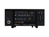
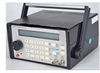
The front panel is equipped with a multiline LCD screen, a large rotary knob, a keypad for entering numbers and selecting functions and two BNC connectors (lower right hand corner). Of the latter the SIG Out connector is the main signal output. The SYNC Out connector is a TTL/CMOS compatible square-wave output. It is a “hardwired” version of the main output and is available in all modes. The SYNC Out swings 0 V to +5 V and is useful for driving digital circuitry.

The wiring of the serial port is a standard female DB9. The SG-100/A is a DCE and connects to the computer with a “straight-through” cable.

The function generator provides ramps, triangles, exponentials, random and sinewave functions in both continuous or triggered operation. The pulse generator provides adjustable amplitudes, offsets, repetition rates and duty cycle in both continuous or triggered operation.

Supplier's Site

Technical Specifications

  ValueTronics International, Inc.
Product Category Signal Generators
Product Number SG-100/A
Product Name Arbitrary Waveform Generator
Device Type Generator
Unlock Full Specs
to access all available technical data

Similar Products

Arbitrary Waveform Generators - 1882473 - RS Components, Ltd.
Specs
User Interface Lan, usb device, usb host
Inputs 2
Maximum 0.5000 MHz
View Details
Waveform Generator - SDG7102A - Siglent Technologies NA, Inc.
Siglent Technologies NA, Inc.
Specs
Device Type Generator
Generator Type Function; Pulse; Sweep
Form Factor Portable
View Details
0.7 to 6 GHz Signal Generator (-60 dBm to +24 dBm) - SSG-R7N6GD-RC - Mini-Circuits
Specs
Device Type Generator
Generator Type Pulse; Sweep
Operating Temperature 32 to 122 F (0 to 50 C)
View Details
20GHz RF Analog Signal Generator - CAMS9K20G - Corech Microwave
Specs
Device Type Generator
Generator Type Signal
Form Factor Portable
View Details