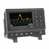
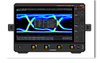
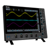
The WAVESURFER 3024 is a 200 MHz, 4 Channel digital oscilloscope from LeCroy. Digital oscilloscopes make use of binary numbers that correspond to samples of the electronic equipment’s voltage. This is in contrast to analog oscilloscopes, which use continually varying voltages. Digital oscilloscopes use an analog-to-digital converter (ADC) to convert the voltages it measures into digital information.
Additional Features:
Up to 4 GS/s sample rate
Long Memory – up to 10 Mpts/Ch
10.1” touch screen display
MAUI Advanced User Interface
Designed for Touch
Built for Simplicity
Made to Solve Advanced Anomaly Detection
Fast Waveform Update
History Mode
WaveScan
Capture, Debug, Analyze, Document
LabNotebook
Sequence Mode
Advanced Active Probe Interface
Math and Measure
Multi-Instrument Capabilities
Protocol Analysis
Serial
Trigger and Decode
Specifications
Analog-Vertical
Bandwidth (@ 50ω): 200 MHz
Rise time: 1.75 ns typical
Vertical Resolution: 8-bits; up to 11-bits with enhanced resolution (ERES)
Sensitivity: 50 ω: 1mV/div - 1 V/div; 1 Mω: 1 mV/div - 10 V/div
DC Gain Accuracy: ± (1.5%) Full Scale, Offset at 0V, > 5mV/div; ± (2.5%) < 5 mV/div
BW Limit 20 MHz
Maximum Input Voltage: 50 ω: 5 Vrms, ±10 V Peak; 1 Mω: 400 V max (DC + Peak AC ≤ 10 kHz)
Input Coupling: 50 ω: DC, GND; 1 Mω: AC, DC, GND
Input Impedance: 50 ω ±2.0%, 1 Mω ±2.0% || 16 pF
Offset Range: 50 ω: 1 mV - 19.8 mV: ±2 V, 20 mV - 100 mV: ±5 V, 102 mV - 198 mV: ±20 V, 200 mV - 1 V: ±50 V
1 Mω: 1 mV - 19.8 mV: ±2 V, 20 mV - 100 mV: ±5 V, 102 mV - 198 mV: ±20 V, 200 mV - 1 V: ±50 V,
1.02 V - 1.98 V: ±200 V, 2 V - 10 V: ±400 V
Offset Accuracy: ± (1.0% of offset value + 1.5%FS + 1 mV)
Analog - Acquisition
Sample Rate (Single-shot): 2 GS/s (4 GS/s interleaved)
Sample Rate (Repetitive): 50 GS/s
Record Length: 10 Mpts/ch (all channels)
Acquisition Modes: Real Time, Roll, RIS (Random Interleaved Sampling), Sequence (Segmented Memory up to 1,000 segments with 1μs minimum intersegment time)
Real Time Timebase Range: 2 ns/div - 50 s/div
RIS Mode Timebase Range: 2 ns/div - 10 ns/div
Roll Mode Timebase Range: Up to 50 s/div (roll mode is user selectable at ≥ 50 ms/div)
Timebase Accuracy: ±10 ppm measured over > 1ms interval
Trigger System
Modes: Auto, Normal, Single, Stop
Sources: Any input channel, External, Ext/5, or line; slope and level unique to each source (except for line trigger)
Coupling: DC, AC, HFREJ, LFREJ
Pre-trigger Delay: 0-100% of full scale
Post-trigger Delay: 0-10,000 Divisions
Hold-off 10ns up to 20s or 1 to 100,000,000 events
Internal Trigger Level Range: ±4.1 Divisions
External Trigger Level Range: Ext: ±610mV, Ext/5: ±3.05V
Trigger Types: Edge, Width, Logic (Pattern), TV (NTSC, PAL, SECAM, HDTV - 720p, 1080i, 1080p), Runt, Slew Rate, Interval (Signal or Pattern), Dropout, Qualified (State or Edge); External and Ext/5 support edge trigger only.
Measure, Zoom and Math Tools
Measurement Parameters: Up to 6 of the following parameters can be calculated at one time on any waveform: Amplitude, Area, Base, Delay, Duty Cycle, Fall Time (90%–10%), Fall Time (80%–20%), Frequency, Maximum, Mean, Minimum, Overshoot+, Overshoot-, Peak-Peak, Period, Phase, Rise Time (10%–90%), Rise Time (20%–80%), RMS, Skew, Standard Deviation, Top, Width+, Width-. Statistics and histicons can be added to measurements. Measurements can be gated.
Zooming: Use front panel QuickZoom button, or use touch screen or mouse to draw a box around the zoom area.
Math Functions: Up to 2 of the following functions can be calculated at one time: Sum, Difference, Product, Ratio, Absolute Value, Average, Derivative, Enhanced Resolution, Envelope, Floor, Integral, Invert, Reciprocal, Rescale, Roof, SinX/x, Square, Square Root, Trend, Zoom and FFT (up to 1 Mpts with power spectrum output and rectangular, VonHann, and FlatTop windows).
Display System
Display Size 10.1” Wide TFT-LCD Touch-Screen
Display Resolution: 1024 x 600
Connectivity
Ethernet Port: 10/100Base-T Ethernet interface (RJ-45 connector)
Removable Storage: (1) MicroSD Port - 8 GB micro SD card installed standard
USB Host Ports: (4) USB Ports Total – (2) Front USB Ports
USB Device Port: (1) USBTMC
GPIB Port (Optional): Supports IEEE – 488.2
External Monitor Port: Standard DB-15 connector (support resolution of 1024x600)
Remote Control: Via Windows Automation, or via Teledyne LeCroy Remote Command Set
Network Communication Standard: GPIB IEEE-488.2 and VICP, USBTMC/USB488
Power Requirements
Voltage: 100 - 240 VAC ± 10% at 50-60 Hz +/-5%; 100 - 120 VAC ± 10% at 400 Hz +/- 5%; Automatic AC Voltage Selection
Power Consumption (Nominal): 100 W / 100 VA
Power Consumption (Max): 150 W / 150 VA (with all PC peripherals, digital leadset and active probes connected to 4 channels)
Environmental
Temperature Operating: 0 °C to 50 °C; Non-Operating: -30 °C to 70 °C
Humidity Operating: 5% to 90% relative humidity (non-condensing) up to ≤ 30 °C, Upper limit derates to 50% relative humidity (non-condensing) at +50 °C
Non-Operating: 5% to 95% relative humidity (non-condensing) as tested per MIL-PRF-28800F
Altitude Operating: 3,048 m (10,000 ft) max at ≤ 25C; Non-Operating: Up to 12,192 meters (40,000 ft)
Physical
Dimensions (HWD) 10.63” H x 14.96” W x 4.92” D (270 mm x 380 mm x 125 mm)
Regulatory
CE Certification Low Voltage Directive 2006/95/EC; EN 61010-1:2010, EN 61010-2-030:2010
EMC Directive 2004/108/EC; EN 61326-1:2013, EN61326-2-1:2013; RoHS2 Directive 2011/65/EU
UL and cUL Listing UL 61010-1, UL 61010-2-030:2010, 3rd Edition; CAN/CSA C22.2 No. 61010-1-12
MAUI-A New Wave of Thinking
MAUI is the most advanced oscilloscope user interface. MAUI is designed for touch; all important oscilloscope controls are accessed through the intuitive touch screen. MAUI is built for simplicity; time saving shortcuts and intuitive dialogs simplify setup. MAUI is made to solve; deep set of debug and analysis tools help identify problems and find solutions quickly.
Advanced Anomaly Detection
Combining a fast waveform update rate of 130,000 waveforms/second with History mode waveform playback and WaveScan search and find, the WaveSurfer 3000 is an outstanding tool for waveform anomaly detection.
Capture, Debug, Analyze, Document
The advanced active probe interface gives tremendous flexibility for capturing all types of signals. Debug, analyze and document problems through the use of powerful math and measurement capabilities, sequence mode segmented memory, and LabNotebook.
Combining a fast waveform update rate of 130,000 waveforms/second with History mode waveform playback, Pass/Fail Mask Testing and WaveScan search and find, the WaveSurfer 3000 is an outstanding tool for waveform anomaly detection. A powerful set of triggering capabilities ensures that once a problem is detected it can be isolated and analyzed.
WaveScan Advanced Search
Locate unusual events in a single capture or scan for an anomaly across many acquisitions over a long period of time. WaveScan provides powerful isolation capabilities that hardware triggers cannot provide.
Select from more than 20 search modes to find events on any analog or digital channel. Since the scanning modes are not simply copies of the hardware triggers, the utility and capability is much higher. There is no frequency trigger in any oscilloscope, yet WaveScan allows for frequency to be quickly scanned, notifying the user upon a shift in frequency. Searching can be done based on measured waveform parameters, runts, and non-monotonic edges as well as digital patterns.
WaveScan quickly and efficiently scans millions of events looking for unusual occurrences. Search and scan results can be seen with annotations directly on the waveform or in the interactive table. Quickly zoom to an event to see more details by simply touching it in the table.
Pass/Fail Mask Testing
Built-in pass/fail mask testing quickly identifies problems and marks the location. A history of the pass/fail results can be displayed on the screen.
There are four different conditions that can be selected to specify a passing condition: All In, All Out, Any In, and Any Out. When a failure is found, one or more of the following actions can be selected to be performed to record the results: save a waveform, stop the acquisition, output and audible alarm, pulse the aux output port, save a hardcopy or even save a LabNotebook entry.
When the acquisition is running, failures are displayed as a red trace, however when the acquisition is stopped, a failure indicator is displayed to clearly show all failing points. Masks can either be created using the offline mask maker utility or created based on a reference waveform and specifying horizontal and vertical deltas.
The WAVESURFER 3024 is a 200 MHz, 4 Channel digital oscilloscope from LeCroy. Digital oscilloscopes make use of binary numbers that correspond to samples of the electronic equipment’s voltage. This is in contrast to analog oscilloscopes, which use continually varying voltages. Digital oscilloscopes use an analog-to-digital converter (ADC) to convert the voltages it measures into digital information.
Additional Features:
- Up to 4 GS/s sample rate
- Long Memory – up to 10 Mpts/Ch
- 10.1” touch screen display
- MAUI Advanced User Interface
- Designed for Touch
- Built for Simplicity
- Made to Solve
Advanced Anomaly Detection
- Fast Waveform Update
- History Mode
- WaveScan
Capture, Debug, Analyze, Document
- LabNotebook
- Sequence Mode
- Advanced Active Probe Interface
- Math and Measure
Multi-Instrument Capabilities
- Protocol Analysis
- Serial
- Trigger and Decode
Specifications
- Analog-Vertical
- Bandwidth (@ 50Ω): 200 MHz
- Rise time: 1.75 ns typical
- Vertical Resolution: 8-bits; up to 11-bits with enhanced resolution (ERES)
- Sensitivity: 50 Ω: 1mV/div - 1 V/div; 1 MΩ: 1 mV/div - 10 V/div
- DC Gain Accuracy: ± (1.5%) Full Scale, Offset at 0V, > 5mV/div; ± (2.5%) < 5 mV/div
- BW Limit 20 MHz
- Maximum Input Voltage: 50 Ω: 5 Vrms, ±10 V Peak; 1 MΩ: 400 V max (DC + Peak AC ≤ 10 kHz)
- Input Coupling: 50 Ω: DC, GND; 1 MΩ: AC, DC, GND
- Input Impedance: 50 Ω ±2.0%, 1 MΩ ±2.0% || 16 pF
- Offset Range: 50 Ω: 1 mV - 19.8 mV: ±2 V, 20 mV - 100 mV: ±5 V, 102 mV - 198 mV: ±20 V, 200 mV - 1 V: ±50 V
- 1 MΩ: 1 mV - 19.8 mV: ±2 V, 20 mV - 100 mV: ±5 V, 102 mV - 198 mV: ±20 V, 200 mV - 1 V: ±50 V,
- 1.02 V - 1.98 V: ±200 V, 2 V - 10 V: ±400 V
- Offset Accuracy: ± (1.0% of offset value + 1.5%FS + 1 mV)
Analog - Acquisition
- Sample Rate (Single-shot): 2 GS/s (4 GS/s interleaved)
- Sample Rate (Repetitive): 50 GS/s
- Record Length: 10 Mpts/ch (all channels)
- Acquisition Modes: Real Time, Roll, RIS (Random Interleaved Sampling), Sequence (Segmented Memory up to 1,000 segments with 1μs minimum intersegment time)
- Real Time Timebase Range: 2 ns/div - 50 s/div
- RIS Mode Timebase Range: 2 ns/div - 10 ns/div
- Roll Mode Timebase Range: Up to 50 s/div (roll mode is user selectable at ≥ 50 ms/div)
- Timebase Accuracy: ±10 ppm measured over > 1ms interval
Trigger System
- Modes: Auto, Normal, Single, Stop
- Sources: Any input channel, External, Ext/5, or line; slope and level unique to each source (except for line trigger)
- Coupling: DC, AC, HFREJ, LFREJ
- Pre-trigger Delay: 0-100% of full scale
- Post-trigger Delay: 0-10,000 Divisions
- Hold-off 10ns up to 20s or 1 to 100,000,000 events
- Internal Trigger Level Range: ±4.1 Divisions
- External Trigger Level Range: Ext: ±610mV, Ext/5: ±3.05V
- Trigger Types: Edge, Width, Logic (Pattern), TV (NTSC, PAL, SECAM, HDTV - 720p, 1080i, 1080p), Runt, Slew Rate, Interval (Signal or Pattern), Dropout, Qualified (State or Edge); External and Ext/5 support edge trigger only.
Measure, Zoom and Math Tools
- Measurement Parameters: Up to 6 of the following parameters can be calculated at one time on any waveform: Amplitude, Area, Base, Delay, Duty Cycle, Fall Time (90%–10%), Fall Time (80%–20%), Frequency, Maximum, Mean, Minimum, Overshoot+, Overshoot-, Peak-Peak, Period, Phase, Rise Time (10%–90%), Rise Time (20%–80%), RMS, Skew, Standard Deviation, Top, Width+, Width-. Statistics and histicons can be added to measurements. Measurements can be gated.
- Zooming: Use front panel QuickZoom button, or use touch screen or mouse to draw a box around the zoom area.
- Math Functions: Up to 2 of the following functions can be calculated at one time: Sum, Difference, Product, Ratio, Absolute Value, Average, Derivative, Enhanced Resolution, Envelope, Floor, Integral, Invert, Reciprocal, Rescale, Roof, SinX/x, Square, Square Root, Trend, Zoom and FFT (up to 1 Mpts with power spectrum output and rectangular, VonHann, and FlatTop windows).
Display System
- Display Size 10.1” Wide TFT-LCD Touch-Screen
- Display Resolution: 1024 x 600
Connectivity
- Ethernet Port: 10/100Base-T Ethernet interface (RJ-45 connector)
- Removable Storage: (1) MicroSD Port - 8 GB micro SD card installed standard
- USB Host Ports: (4) USB Ports Total – (2) Front USB Ports
- USB Device Port: (1) USBTMC
- GPIB Port (Optional): Supports IEEE – 488.2
- External Monitor Port: Standard DB-15 connector (support resolution of 1024x600)
- Remote Control: Via Windows Automation, or via Teledyne LeCroy Remote Command Set
- Network Communication Standard: GPIB IEEE-488.2 and VICP, USBTMC/USB488
Power Requirements
- Voltage: 100 - 240 VAC ± 10% at 50-60 Hz +/-5%; 100 - 120 VAC ± 10% at 400 Hz +/- 5%; Automatic AC Voltage Selection
- Power Consumption (Nominal): 100 W / 100 VA
- Power Consumption (Max): 150 W / 150 VA (with all PC peripherals, digital leadset and active probes connected to 4 channels)
Environmental
- Temperature Operating: 0 °C to 50 °C; Non-Operating: -30 °C to 70 °C
- Humidity Operating: 5% to 90% relative humidity (non-condensing) up to ≤ 30 °C, Upper limit derates to 50% relative humidity (non-condensing) at +50 °C
- Non-Operating: 5% to 95% relative humidity (non-condensing) as tested per MIL-PRF-28800F
- Altitude Operating: 3,048 m (10,000 ft) max at ≤ 25C; Non-Operating: Up to 12,192 meters (40,000 ft)
Physical
- Dimensions (HWD) 10.63” H x 14.96” W x 4.92” D (270 mm x 380 mm x 125 mm)
Regulatory
- CE Certification Low Voltage Directive 2006/95/EC; EN 61010-1:2010, EN 61010-2-030:2010
- EMC Directive 2004/108/EC; EN 61326-1:2013, EN61326-2-1:2013; RoHS2 Directive 2011/65/EU
- UL and cUL Listing UL 61010-1, UL 61010-2-030:2010, 3rd Edition; CAN/CSA C22.2 No. 61010-1-12
MAUI-A New Wave of Thinking
MAUI is the most advanced oscilloscope user interface. MAUI is designed for touch; all important oscilloscope controls are accessed through the intuitive touch screen. MAUI is built for simplicity; time saving shortcuts and intuitive dialogs simplify setup. MAUI is made to solve; deep set of debug and analysis tools help identify problems and find solutions quickly.
Advanced Anomaly Detection
Combining a fast waveform update rate of 130,000 waveforms/second with History mode waveform playback and WaveScan search and find, the WaveSurfer 3000 is an outstanding tool for waveform anomaly detection.
Capture, Debug, Analyze, Document
The advanced active probe interface gives tremendous flexibility for capturing all types of signals. Debug, analyze and document problems through the use of powerful math and measurement capabilities, sequence mode segmented memory, and LabNotebook.
Combining a fast waveform update rate of 130,000 waveforms/second with History mode waveform playback, Pass/Fail Mask Testing and WaveScan search and find, the WaveSurfer 3000 is an outstanding tool for waveform anomaly detection. A powerful set of triggering capabilities ensures that once a problem is detected it can be isolated and analyzed.
WaveScan Advanced Search
Locate unusual events in a single capture or scan for an anomaly across many acquisitions over a long period of time. WaveScan provides powerful isolation capabilities that hardware triggers cannot provide.
Select from more than 20 search modes to find events on any analog or digital channel. Since the scanning modes are not simply copies of the hardware triggers, the utility and capability is much higher. There is no frequency trigger in any oscilloscope, yet WaveScan allows for frequency to be quickly scanned, notifying the user upon a shift in frequency. Searching can be done based on measured waveform parameters, runts, and non-monotonic edges as well as digital patterns.
WaveScan quickly and efficiently scans millions of events looking for unusual occurrences. Search and scan results can be seen with annotations directly on the waveform or in the interactive table. Quickly zoom to an event to see more details by simply touching it in the table.
Pass/Fail Mask Testing
Built-in pass/fail mask testing quickly identifies problems and marks the location. A history of the pass/fail results can be displayed on the screen.
There are four different conditions that can be selected to specify a passing condition: All In, All Out, Any In, and Any Out. When a failure is found, one or more of the following actions can be selected to be performed to record the results: save a waveform, stop the acquisition, output and audible alarm, pulse the aux output port, save a hardcopy or even save a LabNotebook entry.
When the acquisition is running, failures are displayed as a red trace, however when the acquisition is stopped, a failure indicator is displayed to clearly show all failing points. Masks can either be created using the offline mask maker utility or created based on a reference waveform and specifying horizontal and vertical deltas.