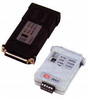
The SRM-9, Async/Sync Short Range Modem, is used for local data distribution, connecting full or half duplex Sync/Async DTEs to other DTEs over unconditioned 4-wire / 2-wire lines. SRM-9 operates at data rates of 32 to 128 kbps in Sync mode and 9.6 to 115.2 kbps in Async mode, at distances up to 16.5 km (10 miles), depending on wire gauge and data rate.
Four models are available:
SRM-9/V.24, with V.24/UP interface (unpowered)
SRM-9/V.24, with V.24 interface (powered)
SRM-9/V.35, with V.35 interface
SRM-9/X.21, with X.21 interface
SRM-9/530, with RS-530 interface Each model has a 25-pin D-type connector for the DTE interface. V.35 interface: a 45 cm cable, with a 25-pin, male connector on one side and a 34-pin, male or female connector on the other side, is supplied.X.21 interface: a 45 cm cable, with a 25-pin male connector on one side, and a 15-pin X.21, female connector on the other side, is supplied.
SRM-9 performs diagnostic loops in compliance with ITU V.54 standard. Two V.54 loops are available: analog loop (V.54 Loop 3) and remote digital loop(V.54 Loop 2). These loops are activated either by a dip-switch or by the DTE interface Circuit 141 (Pin 18) and Circuit 140 (Pin 21). (Loopbacks in SRM-9/X.21 are activated by dipswitch only.) A proprietary local digital loop is available and can be activated only by the modem's switches. This loop connects the local RD to the TD. A TEST LED lights when any diagnostic loop is ON.
SRM-9 includes a built-in BERT according to the V.52 standard for testing link communication. The internal BERT is activated by the dip-switch (PATT). The BERT checks the received data, and the error LED (ERR) lights when errors are detected.
Asynchronous transmission is provided by internal conversion from Async to Sync in compliance with the ITU V.22 bis standard. Different Async formats are switch selectable.
In Synchronous mode, transmit timing can be provided by three alternative sources:
Internal oscillator
External clock
Loopback clock derived from the receive signal.
The modem's carrier can be set for either continuous operation (point-to-point application) or controlled operation by the RTS signal (multipoint application or passing control signals end-to-end).
The low transmit level minimizes crosstalk on adjacent circuits within the same cable. Data is transmitted and received at a balanced impedance, ensuring high immunity to circuit noise. Additionally,SRM-9 is coupled to the line through isolation transformers, which protect against AC or DC overvoltages.
SRM-9/V.24/UP/RS-232 interface can operate without a power supply, using ultra-low power from the standard V.24/RS-232 data and control signals. When the DTE cannot provide the power required, SRM-9's power consumption can be significantly reduced by disabling the LEDs (setting via dip-switch).
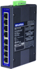
Six LED indicators are available to facilitate diagnostics: TST, DCD, TD, RTS, RD, ERR.
The line interface is a 5-screw clip terminal block or an RJ-45 connector.
The SRM-9, Async/Sync Short Range Modem, is used for local data distribution, connecting full or half duplex Sync/Async DTEs to other DTEs over unconditioned 4-wire / 2-wire lines. SRM-9 operates at data rates of 32 to 128 kbps in Sync mode and 9.6 to 115.2 kbps in Async mode, at distances up to 16.5 km (10 miles), depending on wire gauge and data rate.
- Four models are available:
- SRM-9/V.24, with V.24/UP interface (unpowered)
- SRM-9/V.24, with V.24 interface (powered)
- SRM-9/V.35, with V.35 interface
- SRM-9/X.21, with X.21 interface
- SRM-9/530, with RS-530 interface
Each model has a 25-pin D-type connector for the DTE interface. V.35 interface: a 45 cm cable, with a 25-pin, male connector on one side and a 34-pin, male or female connector on the other side, is supplied.X.21 interface: a 45 cm cable, with a 25-pin male connector on one side, and a 15-pin X.21, female connector on the other side, is supplied.
- SRM-9 performs diagnostic loops in compliance with ITU V.54 standard. Two V.54 loops are available: analog loop (V.54 Loop 3) and remote digital loop(V.54 Loop 2). These loops are activated either by a dip-switch or by the DTE interface Circuit 141 (Pin 18) and Circuit 140 (Pin 21). (Loopbacks in SRM-9/X.21 are activated by dipswitch only.) A proprietary local digital loop is available and can be activated only by the modem's switches. This loop connects the local RD to the TD. A TEST LED lights when any diagnostic loop is ON.
- SRM-9 includes a built-in BERT according to the V.52 standard for testing link communication. The internal BERT is activated by the dip-switch (PATT). The BERT checks the received data, and the error LED (ERR) lights when errors are detected.
- Asynchronous transmission is provided by internal conversion from Async to Sync in compliance with the ITU V.22 bis standard. Different Async formats are switch selectable.
- In Synchronous mode, transmit timing can be provided by three alternative sources:
- Loopback clock derived from the receive signal.
- The modem's carrier can be set for either continuous operation (point-to-point application) or controlled operation by the RTS signal (multipoint application or passing control signals end-to-end).
- The low transmit level minimizes crosstalk on adjacent circuits within the same cable. Data is transmitted and received at a balanced impedance, ensuring high immunity to circuit noise. Additionally,SRM-9 is coupled to the line through isolation transformers, which protect against AC or DC overvoltages.
- SRM-9/V.24/UP/RS-232 interface can operate without a power supply, using ultra-low power from the standard V.24/RS-232 data and control signals. When the DTE cannot provide the power required, SRM-9's power consumption can be significantly reduced by disabling the LEDs (setting via dip-switch).
- Six LED indicators are available to facilitate diagnostics: TST, DCD, TD, RTS, RD, ERR.
- The line interface is a 5-screw clip terminal block or an RJ-45 connector.