RAD Data Communications, Inc.Sync/Async Short Range ModemSRM-8V
Description
FEATURES
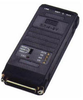
The SRM-8V, Async/Sync Short Range Modem, is used for local data distribution, connecting full or half duplex Sync/Async DTEs to computers over unconditioned 4-wire lines. SRM-8V operates at data rates up to 38.4 kbps, and at distances up to 19 km (11.7 miles), depending on wire gauge and data rate (see Table 1).
SRM-8V performs diagnostic loops in compliance with the ITU V.54 standard. Two V.54 loops are available: analog loop (V.54 Loop 3) and remote digital loop (V.54 Loop 2). These loops are activated by either a 3-position switch or by the DTE interface Circuit 141 (Pin 18) and Circuit 140 (Pin 21). A TEST LED lights when any of the diagnostic loops are ON.
Asynchronous transmission is provided by internal conversion from Sync to Async, in compliance with the ITU V.22 bis standard. Different Async formats are switch-selectable.
In Synchronous mode, transmit timing can be provided by three alternative sources:
Internal oscillator
External clock
Loopback clock derived from the receive signal.
The modem's carrier can be strapped for either continuous operation (point-to-point application) or switched operation, controlled by the RTS signal (multipoint application, or passing control signals end-to-end).
DTE/DCE switch enables direct connection to DTE or DCE equipment, eliminating the necessity for a cross cable. Note: When SW2 is set to DTE, the ANA switch (SW7-2) should be strapped to DIS.
The low transmit level minimizes crosstalk onto adjacent circuits within the same cable. Data is transmitted and received at a balanced impedance, ensuring high immunity to circuit noise. Additionally, SRM-8V is coupled to the line through isolation transformers which protect against AC or DC overvoltages.
SRM-8V can operate without a power supply, by using ultra-low power from the standard V.24/RS-232 data and control signals. When the DTE cannot provide the power required, SRM-8V's power consumption can be significantly reduced by disabling the LEDs (strap-selectable).
The line interface consists of two independent connectors: one is a 5-screw terminal block, the other is a selectable RJ-12 or RJ-45 connector (see Ordering).
Five LED indicators are available to facilitate diagnostics: Test, Data Carrier Detect, Transmit Data, Request to Send, and Receive Data.
Data Connect Enterprise, Inc.
Done
Description
FEATURES
The SRM-8V, Async/Sync Short Range Modem, is used for local data distribution, connecting full or half duplex Sync/Async DTEs to computers over unconditioned 4-wire lines. SRM-8V operates at data rates up to 38.4 kbps, and at distances up to 19 km (11.7 miles), depending on wire gauge and data rate (see Table 1).
SRM-8V performs diagnostic loops in compliance with the ITU V.54 standard. Two V.54 loops are available: analog loop (V.54 Loop 3) and remote digital loop (V.54 Loop 2). These loops are activated by either a 3-position switch or by the DTE interface Circuit 141 (Pin 18) and Circuit 140 (Pin 21). A TEST LED lights when any of the diagnostic loops are ON.
Asynchronous transmission is provided by internal conversion from Sync to Async, in compliance with the ITU V.22 bis standard. Different Async formats are switch-selectable.
In Synchronous mode, transmit timing can be provided by three alternative sources:
Internal oscillator
External clock
Loopback clock derived from the receive signal.
The modem's carrier can be strapped for either continuous operation (point-to-point application) or switched operation, controlled by the RTS signal (multipoint application, or passing control signals end-to-end).
DTE/DCE switch enables direct connection to DTE or DCE equipment, eliminating the necessity for a cross cable. Note: When SW2 is set to DTE, the ANA switch (SW7-2) should be strapped to DIS.
The low transmit level minimizes crosstalk onto adjacent circuits within the same cable. Data is transmitted and received at a balanced impedance, ensuring high immunity to circuit noise. Additionally, SRM-8V is coupled to the line through isolation transformers which protect against AC or DC overvoltages.
SRM-8V can operate without a power supply, by using ultra-low power from the standard V.24/RS-232 data and control signals. When the DTE cannot provide the power required, SRM-8V's power consumption can be significantly reduced by disabling the LEDs (strap-selectable).
The line interface consists of two independent connectors: one is a 5-screw terminal block, the other is a selectable RJ-12 or RJ-45 connector (see Ordering).
Five LED indicators are available to facilitate diagnostics: Test, Data Carrier Detect, Transmit Data, Request to Send, and Receive Data.
FEATURES
The SRM-8V, Async/Sync Short Range Modem, is used for local data distribution, connecting full or half duplex Sync/Async DTEs to computers over unconditioned 4-wire lines. SRM-8V operates at data rates up to 38.4 kbps, and at distances up to 19 km (11.7 miles), depending on wire gauge and data rate (see Table 1).
SRM-8V performs diagnostic loops in compliance with the ITU V.54 standard. Two V.54 loops are available:
analog loop (V.54 Loop 3) and
remote digital loop (V.54 Loop 2). These loops are activated by either a 3-position switch or by the DTE interface Circuit 141 (Pin 18) and Circuit 140 (Pin 21).
A TEST LED lights when any of the diagnostic loops are ON.
Asynchronous transmission is provided by internal conversion from Sync to Async, in compliance with the ITU V.22 bis standard. Different Async formats are switch-selectable.
In Synchronous mode, transmit timing can be provided by three alternative sources:
Internal oscillator
External clock
Loopback clock derived from the receive signal.
The modem's carrier can be strapped for either continuous operation (point-to-point application) or switched operation, controlled by the RTS signal (multipoint application, or passing control signals end-to-end).
DTE/DCE switch enables direct connection to DTE or DCE equipment, eliminating the necessity for a cross cable.
Note: When SW2 is set to DTE, the ANA switch (SW7-2) should be strapped to DIS.
The low transmit level minimizes crosstalk onto adjacent circuits within the same cable. Data is transmitted and received at a balanced impedance, ensuring high immunity to circuit noise. Additionally, SRM-8V is coupled to the line through isolation transformers which protect against AC or DC overvoltages.
SRM-8V can operate without a power supply, by using ultra-low power from the standard V.24/RS-232 data and control signals. When the DTE cannot provide the power required, SRM-8V's power consumption can be significantly reduced by disabling the LEDs (strap-selectable).
The line interface consists of two independent connectors: one is a 5-screw terminal block, the other is a selectable RJ-12 or RJ-45 connector (see Ordering).
Five LED indicators are available to facilitate diagnostics: Test, Data Carrier Detect, Transmit Data, Request to Send, and Receive Data.