FEATURES
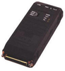
The SRM-8H, High Speed Short Range Modem, is used for local data distribution, connecting full duplex Sync or Async DTEs, computers or controllers over unconditioned 4-wire dedicated lines. SRM-8H operates at data rates of 56 or 64 kbps, at distances up to 10 km (6 miles), according to the wire gauge and data rate.
Four models are available:
SRM-8H/V.24, with V.24/RS-232 interface
SRM-8H/V.35, with V.35 interface
SRM-8H/X.21, with X.21 interface
SRM-8H/530, with RS-530 interface. Each model has a 25-pin D-type connector for the DTE interface. V.35 interface: a 45 cm (17.7") cable is supplied, with a 25-pin, female connector on one side and a 34-pin, male or female connector on the other side.X.21 interface: a 45 cm (17.7") cable is supplied, with a 25-pin male connector on one side, and a 15-pin X.21, male or female connector on the other side.
Four LED indicators are available to facilitate diagnostics: Power, Test, Data Carrier Detect and Transmit Data.
Transmit timing is provided via three sources: an internal oscillator, an external clock or a loopback clock derived from the receive signal. For the X.21 interface, transmit timing can be either via internal clock or recovered from the line.
The modem's carrier is strap-selectable for either continuous operation, or switched operation for passing control signals end-to-end. Switched operation is controlled by the RTS signal.
SRM-8H performs diagnostic loops in compliance with the ITU V.54 standard. Two V.54 loops are available: local analog loop (V.54, loop 3) and remote digital loop (V.54, loop 2). The loops are activated by a 3-position switch in all models, or by the DTE interface Circuit 141 (Pin 18) and Circuit 140 (Pin 21) in all models except SRM-8H/X.21. The Test LED lights when any diagnostic loop is active.
The low transmit level minimizes crosstalk onto adjacent circuits within the same cable. Data is transmitted and received using a balanced interface, ensuring high immunity to circuit noise. Additionally, SRM-8H is coupled to the dedicated line through isolation transformers which, in conjunction with other circuitry, protect against AC or DC overvoltages.
The line interface consists of two independent connectors: a 5-screw terminal block, and a selectable RJ-11 or RJ-45 connector (see Ordering).
Power is supplied from a standard, wall-mounted power supply, 300 mA (center - positive; sleeve - negative).
SRM-8H is also available as a card for mounting in a 19" modem rack (see CMN-16 card, CMN-C8H data sheet
FEATURES
The SRM-8H, High Speed Short Range Modem, is used for local data distribution, connecting full duplex Sync or Async DTEs, computers or controllers over unconditioned 4-wire dedicated lines. SRM-8H operates at data rates of 56 or 64 kbps, at distances up to 10 km (6 miles), according to the wire gauge and data rate.
- Four models are available:
- SRM-8H/V.24, with V.24/RS-232 interface
- SRM-8H/V.35, with V.35 interface
- SRM-8H/X.21, with X.21 interface
- SRM-8H/530, with RS-530 interface.
Each model has a 25-pin D-type connector for the DTE interface. V.35 interface: a 45 cm (17.7") cable is supplied, with a 25-pin, female connector on one side and a 34-pin, male or female connector on the other side.X.21 interface: a 45 cm (17.7") cable is supplied, with a 25-pin male connector on one side, and a 15-pin X.21, male or female connector on the other side.
- Four LED indicators are available to facilitate diagnostics: Power, Test, Data Carrier Detect and Transmit Data.
- Transmit timing is provided via three sources: an internal oscillator, an external clock or a loopback clock derived from the receive signal. For the X.21 interface, transmit timing can be either via internal clock or recovered from the line.
- The modem's carrier is strap-selectable for either continuous operation, or switched operation for passing control signals end-to-end. Switched operation is controlled by the RTS signal.
- SRM-8H performs diagnostic loops in compliance with the ITU V.54 standard. Two V.54 loops are available: local analog loop (V.54, loop 3) and remote digital loop (V.54, loop 2). The loops are activated by a 3-position switch in all models, or by the DTE interface Circuit 141 (Pin 18) and Circuit 140 (Pin 21) in all models except SRM-8H/X.21. The Test LED lights when any diagnostic loop is active.
- The low transmit level minimizes crosstalk onto adjacent circuits within the same cable. Data is transmitted and received using a balanced interface, ensuring high immunity to circuit noise. Additionally, SRM-8H is coupled to the dedicated line through isolation transformers which, in conjunction with other circuitry, protect against AC or DC overvoltages.
- The line interface consists of two independent connectors: a 5-screw terminal block, and a selectable RJ-11 or RJ-45 connector (see Ordering).
- Power is supplied from a standard, wall-mounted power supply, 300 mA (center - positive; sleeve - negative).
- SRM-8H is also available as a card for mounting in a 19" modem rack (see CMN-16 card, CMN-C8H data sheet