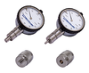
Mini-Circuits INTERFACE-CHECK-GAGE-SMA ACUDIAL-SMA

Description
Mini-Circuits’ ACUDIAL-SMA Series connector gage kit is a push on type Gage designed to measure the center contact pin and dielectric location of type SMA female and male connectors per MIL-PRF-39012 class 2. The ACUDIAL-SMA Gage kit consists of: 1. a dial indicator assembly graduated in 0.001 increments with integral female and male measurement bushings. 2. female and male master gage 3. Instruction manual all contained in a solid wooden instrument case (12 x 7 x 3.5 inches) Before checking the interface dimensions of any connector the dial indicator is set to zero by means of a master gage. After zeroing , the connector is engaged on the on the male or female bushing of the gage depending upon the gender of connector The resultant reading is the actual deviation from the nominal (mean) dimension as indicated in following table 1. APPLICATION All the coaxial connectors mounted on device cables or any test equipment should always be gaged before mating to insure compliance. Such check helps in averting interfered matting and to assure proper electrical performance and produce accurate test data and preventing damage to the device being tested. The ACUDIAL-SMA Gage kit is the right tool for all of these situations, and can also be used for performing production checkout, incoming inspections, routine quality control, and general laboratory operations. COMPLIANCE y Per ASME B89.1.10M-2001, C5.12 y Per ASME B89.1.10M-2001, Table 3 y Performance standards are in compliance with ANSI/NCSL Z540-1 and iso 10012-1 REV. B ECO-023951 MCL NY 250221 www.minicircuits.com P.O. Box 350166, Brooklyn, NY 11235-0003 (718) 934-4500 sales@minicircuits.c om PAGE 1 OF 2 CALIBRATION SOLUTIONS SMA Connector Gage Kit ACUDIAL-SMA SPECIFICATIONS SMA CONTACT PIN LOCATION Table 1. Contact Pin Location for SMA Connectors Specification FP FD 0.010 0.000 Max. 0.000 MIL-STD-348A MP MD CLASS 2 0.010 0.000 Max. 0.000 SMA Connector Gage Specifications Characteristics Limits Comments Gage Resolution 0.0001” 1/5 Least dial graduation MASTER GAGES Gage Calibration 1 Least dial graduation plus 0.000250 0.00075” Accuracy measurement guardband Gage 0.0001” 1/5 Least dial graduation Repeatability Master Accuracy 0.0000125” 0.0001 Range Fig 2. Gaging a Female SMA Connector Total Uncertainty Table 2. Gage Dimensions Female RSS 0.000763319 (Root sum of squares) Specification Min. "A" Max. "A" Mean "A" Worst Case 0.0009625 (Sum of all units) +0.000 0.206 0.006 0.007 0.0065 -0.001 Fig 3. Gaging a Male SMA Connector Table 3. Gage Dimensions Male Specification Min. "B" Max. "B" Mean "B" +0.000 0.210 0.000 0.000 0.0000 -0.000 NOTES A. Performance and quality attributes and conditions not expressly stated in this specification document are intended to be excluded and do not form a part of this specification document. B. Electrical specifications and performance data contained in this specification document are based on Mini-Circuit’s applicable established test performance criteria and measurement instructions. C. The parts covered by this specification document are subject to Mini-Circuits standard limited warranty and terms and conditions (collectively, “Standard Terms”); Purchasers of this part are entitled to the rights and benefits contained therein. For a full statement of the standard. Terms and the exclusive rights and remedies thereunder, please visit Mini-Circuits’ website at www.minicircuits.com /MCLStore/terms.jsp www.minicircuits.com P.O. Box 350166, Brooklyn, NY 11235-0003 (718) 934-4500 sales@minicircuits.c om PAGE 2 OF 2
Request a Quote Datasheet
Description
Mini-Circuits’ ACUDIAL-SMA Series connector gage kit is a push on type Gage designed to measure the center contact pin and dielectric location of type SMA female and male connectors per MIL-PRF-39012 class 2. The ACUDIAL-SMA Gage kit consists of: 1. a dial indicator assembly graduated in 0.001 increments with integral female and male measurement bushings. 2. female and male master gage 3. Instruction manual all contained in a solid wooden instrument case (12 x 7 x 3.5 inches) Before checking the interface dimensions of any connector the dial indicator is set to zero by means of a master gage. After zeroing , the connector is engaged on the on the male or female bushing of the gage depending upon the gender of connector The resultant reading is the actual deviation from the nominal (mean) dimension as indicated in following table 1. APPLICATION All the coaxial connectors mounted on device cables or any test equipment should always be gaged before mating to insure compliance. Such check helps in averting interfered matting and to assure proper electrical performance and produce accurate test data and preventing damage to the device being tested. The ACUDIAL-SMA Gage kit is the right tool for all of these situations, and can also be used for performing production checkout, incoming inspections, routine quality control, and general laboratory operations. COMPLIANCE y Per ASME B89.1.10M-2001, C5.12 y Per ASME B89.1.10M-2001, Table 3 y Performance standards are in compliance with ANSI/NCSL Z540-1 and iso 10012-1 REV. B ECO-023951 MCL NY 250221 www.minicircuits.com P.O. Box 350166, Brooklyn, NY 11235-0003 (718) 934-4500 sales@minicircuits.c om PAGE 1 OF 2 CALIBRATION SOLUTIONS SMA Connector Gage Kit ACUDIAL-SMA SPECIFICATIONS SMA CONTACT PIN LOCATION Table 1. Contact Pin Location for SMA Connectors Specification FP FD 0.010 0.000 Max. 0.000 MIL-STD-348A MP MD CLASS 2 0.010 0.000 Max. 0.000 SMA Connector Gage Specifications Characteristics Limits Comments Gage Resolution 0.0001” 1/5 Least dial graduation MASTER GAGES Gage Calibration 1 Least dial graduation plus 0.000250 0.00075” Accuracy measurement guardband Gage 0.0001” 1/5 Least dial graduation Repeatability Master Accuracy 0.0000125” 0.0001 Range Fig 2. Gaging a Female SMA Connector Total Uncertainty Table 2. Gage Dimensions Female RSS 0.000763319 (Root sum of squares) Specification Min. "A" Max. "A" Mean "A" Worst Case 0.0009625 (Sum of all units) +0.000 0.206 0.006 0.007 0.0065 -0.001 Fig 3. Gaging a Male SMA Connector Table 3. Gage Dimensions Male Specification Min. "B" Max. "B" Mean "B" +0.000 0.210 0.000 0.000 0.0000 -0.000 NOTES A. Performance and quality attributes and conditions not expressly stated in this specification document are intended to be excluded and do not form a part of this specification document. B. Electrical specifications and performance data contained in this specification document are based on Mini-Circuit’s applicable established test performance criteria and measurement instructions. C. The parts covered by this specification document are subject to Mini-Circuits standard limited warranty and terms and conditions (collectively, “Standard Terms”); Purchasers of this part are entitled to the rights and benefits contained therein. For a full statement of the standard. Terms and the exclusive rights and remedies thereunder, please visit Mini-Circuits’ website at www.minicircuits.com /MCLStore/terms.jsp www.minicircuits.com P.O. Box 350166, Brooklyn, NY 11235-0003 (718) 934-4500 sales@minicircuits.c om PAGE 2 OF 2
Request a Quote Datasheet

Suppliers

Company
Product
Description
Supplier Links
INTERFACE-CHECK-GAGE-SMA - ACUDIAL-SMA - Mini-Circuits
Brooklyn, NY, United States
INTERFACE-CHECK-GAGE-SMA
ACUDIAL-SMA
INTERFACE-CHECK-GAGE-SMA ACUDIAL-SMA
Mini-Circuits’ ACUDIAL-SMA Series connector gage kit is a push on type Gage designed to measure the center contact pin and dielectric location of type SMA female and male connectors per MIL-PRF-39012 class 2. The ACUDIAL-SMA Gage kit consists of: 1. a dial indicator assembly graduated in 0.001 increments with integral female and male measurement bushings. 2. female and male master gage 3. Instruction manual all contained in a solid wooden instrument case (12 x 7 x 3.5 inches) Before checking the interface dimensions of any connector the dial indicator is set to zero by means of a master gage. After zeroing , the connector is engaged on the on the male or female bushing of the gage depending upon the gender of connector The resultant reading is the actual deviation from the nominal (mean) dimension as indicated in following table 1. APPLICATION All the coaxial connectors mounted on device cables or any test equipment should always be gaged before mating to insure compliance. Such check helps in averting interfered matting and to assure proper electrical performance and produce accurate test data and preventing damage to the device being tested. The ACUDIAL-SMA Gage kit is the right tool for all of these situations, and can also be used for performing production checkout, incoming inspections, routine quality control, and general laboratory operations. COMPLIANCE y Per ASME B89.1.10M-2001, C5.12 y Per ASME B89.1.10M-2001, Table 3 y Performance standards are in compliance with ANSI/NCSL Z540-1 and iso 10012-1 REV. B ECO-023951 MCL NY 250221 www.minicircuits.com P.O. Box 350166, Brooklyn, NY 11235-0003 (718) 934-4500 sales@minicircuits.c om PAGE 1 OF 2 CALIBRATION SOLUTIONS SMA Connector Gage Kit ACUDIAL-SMA SPECIFICATIONS SMA CONTACT PIN LOCATION Table 1. Contact Pin Location for SMA Connectors Specification FP FD 0.010 0.000 Max. 0.000 MIL-STD-348A MP MD CLASS 2 0.010 0.000 Max. 0.000 SMA Connector Gage Specifications Characteristics Limits Comments Gage Resolution 0.0001” 1/5 Least dial graduation MASTER GAGES Gage Calibration 1 Least dial graduation plus 0.000250 0.00075” Accuracy measurement guardband Gage 0.0001” 1/5 Least dial graduation Repeatability Master Accuracy 0.0000125” 0.0001 Range Fig 2. Gaging a Female SMA Connector Total Uncertainty Table 2. Gage Dimensions Female RSS 0.000763319 (Root sum of squares) Specification Min. "A" Max. "A" Mean "A" Worst Case 0.0009625 (Sum of all units) +0.000 0.206 0.006 0.007 0.0065 -0.001 Fig 3. Gaging a Male SMA Connector Table 3. Gage Dimensions Male Specification Min. "B" Max. "B" Mean "B" +0.000 0.210 0.000 0.000 0.0000 -0.000 NOTES A. Performance and quality attributes and conditions not expressly stated in this specification document are intended to be excluded and do not form a part of this specification document. B. Electrical specifications and performance data contained in this specification document are based on Mini-Circuit’s applicable established test performance criteria and measurement instructions. C. The parts covered by this specification document are subject to Mini-Circuits standard limited warranty and terms and conditions (collectively, “Standard Terms”); Purchasers of this part are entitled to the rights and benefits contained therein. For a full statement of the standard. Terms and the exclusive rights and remedies thereunder, please visit Mini-Circuits’ website at www.minicircuits.com /MCLStore/terms.jsp www.minicircuits.com P.O. Box 350166, Brooklyn, NY 11235-0003 (718) 934-4500 sales@minicircuits.c om PAGE 2 OF 2

Mini-Circuits’ ACUDIAL-SMA Series connector gage kit is a push on type Gage designed to measure the center contact pin and dielectric location of type SMA female and male connectors per MIL-PRF-39012 class 2. The ACUDIAL-SMA Gage kit consists of: 1. a dial indicator assembly graduated in 0.001 increments with integral female and male measurement bushings. 2. female and male master gage 3. Instruction manual all contained in a solid wooden instrument case (12 x 7 x 3.5 inches) Before checking the interface dimensions of any connector the dial indicator is set to zero by means of a master gage. After zeroing , the connector is engaged on the on the male or female bushing of the gage depending upon the gender of connector The resultant reading is the actual deviation from the nominal (mean) dimension as indicated in following table 1. APPLICATION All the coaxial connectors mounted on device cables or any test equipment should always be gaged before mating to insure compliance. Such check helps in averting interfered matting and to assure proper electrical performance and produce accurate test data and preventing damage to the device being tested. The ACUDIAL-SMA Gage kit is the right tool for all of these situations, and can also be used for performing production checkout, incoming inspections, routine quality control, and general laboratory operations. COMPLIANCE y Per ASME B89.1.10M-2001, C5.12 y Per ASME B89.1.10M-2001, Table 3 y Performance standards are in compliance with ANSI/NCSL Z540-1 and iso 10012-1 REV. B ECO-023951 MCL NY 250221 www.minicircuits.com P.O. Box 350166, Brooklyn, NY 11235-0003 (718) 934-4500 sales@minicircuits.com PAGE 1 OF 2 CALIBRATION SOLUTIONS SMA Connector Gage Kit ACUDIAL-SMA SPECIFICATIONS SMA CONTACT PIN LOCATION Table 1. Contact Pin Location for SMA Connectors Specification FP FD 0.010 0.000 Max. 0.000 MIL-STD-348A MP MD CLASS 2 0.010 0.000 Max. 0.000 SMA Connector Gage Specifications Characteristics Limits Comments Gage Resolution 0.0001” 1/5 Least dial graduation MASTER GAGES Gage Calibration 1 Least dial graduation plus 0.000250 0.00075” Accuracy measurement guardband Gage 0.0001” 1/5 Least dial graduation Repeatability Master Accuracy 0.0000125” 0.0001 Range Fig 2. Gaging a Female SMA Connector Total Uncertainty Table 2. Gage Dimensions Female RSS 0.000763319 (Root sum of squares) Specification Min. "A" Max. "A" Mean "A" Worst Case 0.0009625 (Sum of all units) +0.000 0.206 0.006 0.007 0.0065 -0.001 Fig 3. Gaging a Male SMA Connector Table 3. Gage Dimensions Male Specification Min. "B" Max. "B" Mean "B" +0.000 0.210 0.000 0.000 0.0000 -0.000 NOTES A. Performance and quality attributes and conditions not expressly stated in this specification document are intended to be excluded and do not form a part of this specification document. B. Electrical specifications and performance data contained in this specification document are based on Mini-Circuit’s applicable established test performance criteria and measurement instructions. C. The parts covered by this specification document are subject to Mini-Circuits standard limited warranty and terms and conditions (collectively, “Standard Terms”); Purchasers of this part are entitled to the rights and benefits contained therein. For a full statement of the standard. Terms and the exclusive rights and remedies thereunder, please visit Mini-Circuits’ website at www.minicircuits.com/MCLStore/terms.jsp www.minicircuits.com P.O. Box 350166, Brooklyn, NY 11235-0003 (718) 934-4500 sales@minicircuits.com PAGE 2 OF 2
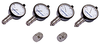
Supplier's Site Datasheet

Technical Specifications

  Mini-Circuits
Product Category Pressure Gauges
Product Number ACUDIAL-SMA
Product Name INTERFACE-CHECK-GAGE-SMA
Type Gauge
Unlock Full Specs
to access all available technical data

Similar Products