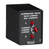


The ARP Series is used in systems where equal run time for two motors is desirable. The selector switch allows selection of alternation of either load for continuous operation. LED’s indicate the status of the output relay. This versatile series may be front panel mounted (BZ1 accessory required) or 35 mm DIN rail mounted with an accessory socket. Operation Alternating: When the rotary switch is in the “alternate” position, alternating operation of Load A and Load B occurs upon the opening of the control switch S1. To terminate alternating operation and cause only the selected load to operate, rotate the switch to position “A” to lock Load A or position “B” to lock Load B. The LEDs indicate the status of the internal relay and which load is selected to operate.Note: Input voltage must be applied at all times for proper alternation. The use of a solid-state control switch for S1 may not initiate alternation correctly. S1 voltage must be from the same supply as the unit’s input voltage (see connection diagrams on datasheet). Loss of input voltage resets the unit; Load A becomes the lead load for the next operation.Duplexing (Cross Wired): Duplexing models operate the same as alternating relays and when both the Control (S1) and Lag Load (S2) Switches are closed, Load A and Load B energize simultaneously.The DPDT 8-pin, cross-wired option, allows extra system load capacity through simultaneous operation of both motors when needed. Relay contacts are not isolated.
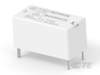
Impulse Relay SPDT (1 Form C) 120VAC Coil Socketable
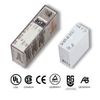
Industrial Relays 200:5 1inW DONUT
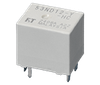
RELAY IMPULSE SPDT 10A 120V
| Littelfuse, Inc. | DigiKey | VAST STOCK CO., LIMITED | Acme Chip Technology Co., Limited | |
|---|---|---|---|---|
| Product Category | Electromechanical Relays | Electromechanical Relays | Electromechanical Relays | High Voltage Relays |
| Product Number | ARP41 | 5666-ARP41-ND | ARP41 | ARP41 |
| Product Name | Alternating Relay | Power Relays, Over 2 Amps | Industrial Relays | Relays - Power Relays, Over 2 Amps |
| Mounting | Socket or Plug-in Style; Plug-in socket | Socketable | Socket or Plug-in Style; Socketable | |
| Poles | Single Pole (SP) | Single Pole (SP) | ||
| Throw | Double Throw | Double Throw | ||
| Features | Visual Indicator |