The switched ports are transparent to all data.
The DTR / DCD lines of the RS530 interface are switched based on desired position, TXD, TXC are passed through the unit from IN to OUT at all times.
Channels 1 & 2 are switched independently.
Switch data activity may be monitored via the Remote port.
Switch position can be interpreted / read by status pins that are part of the Remote port.
Switch position is managed by the device connected to the Remote port, exclusively.
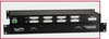
Front panel LEDs display the current switch position and power status.
Switches are latching and maintain their position during power loss.
Twelve pins per channel are supported (4 pins switched, 8 pins bussed through).
Electro Standards Laboratories
Done
Datasheet
Description
The switched ports are transparent to all data.
The DTR / DCD lines of the RS530 interface are switched based on desired position, TXD, TXC are passed through the unit from IN to OUT at all times.
Channels 1 & 2 are switched independently.
Switch data activity may be monitored via the Remote port.
Switch position can be interpreted / read by status pins that are part of the Remote port.
Switch position is managed by the device connected to the Remote port, exclusively.
Front panel LEDs display the current switch position and power status.
Switches are latching and maintain their position during power loss.
Twelve pins per channel are supported (4 pins switched, 8 pins bussed through).