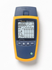
1) The Model 700 display consists of 14 "Tri-State" LEDs, each of which actually can display signal status in three colors (red, green, orange). The LEDs can also be OFF (not illuminated), therefore that means each of the 14 LED's can give you four states of information ... totaling 56 pieces of interface information! SIMULTANEOUSLY!
2) The four pieces of information for each signal are easy to understand. RED means the signal is in the "CONTROL OFF" state. GREEN means the signal is in the 'CONTROL ON" state. ORANGE means there is a proper clock/timing signal or a proper data stream signal on that line. LED OFF (not illuminated) means the signal is either too weak or that no signal is present.
3) A manual accompanies each unit and provides application assistance. Need more help? Contact Electro Standards, provide the serial number of your Model 700, state your application and question, and you will receive a helpful answer.
4) Front panel mini-switches, signal access posts, and mini-patchcords supplied with the unit allow you to gyrate/manipulate the serial connections and signal placement as required to get your two pieces of equipment properly connected.
5) Here is the best: When you have established a pin/signal interconnection that works between your two devices, read the jumper connections and the mini-switch connections that you observe on the front panel of the Model 700 and you have the design for the required interface cable!
Conclusion: Many serial data interface problems and data cable designs can be pinpointed and resolved with the Model 700.
Model 700 EIA RS-232 Interface Analyzer is a diagnostic tool designed for use at the Standard EIA RS-232 or CCITT V.35 data interface of modems, multiplexers, terminals, and computers. It is simply inserted in series between the DTE (Data Terminal Equipment) and the DCE (Data Communication Equipment) to provide access to and monitoring of all data, timing, and control signals.
The Model 700 breakout box is of optimum design. It utilizes state-of-the-art tri-state light emitting diodes to clearly display polarity, activity and validity of all interface signals. Miniature rocker switches allow the user to program a 'make' or 'break' for each signal at the DCE/DTE interface. Mini-patchcords are provided for cross-patching or loopback patching of signals at the front panel test point array.
A complete table of EIA/CCITT standard interface signal descriptions is provided inside the unit for ready reference during testing. A covered compartment provides secure storage for mini-patchcords and an EIA ribbon cable. The Model 700 breakout box is battery powered for complete portability, pocket sized for convenience, and packaged in a study aluminum case with metal hinge for durability in field use.
| Electro Standards Laboratories | |
|---|---|
| Product Category | Network Test Equipment |
| Product Number | M700 |
| Product Name | EIA RS-232 Interface Analyzer |
| Equipment Type | Breakout Boxes |
| Network Protocol | RS232 |
| Number of Ports | 2 |
| Form Factor | Notebook |