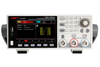
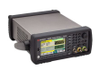
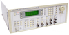
Amprobe Test Tools Arbitrary Waveform Generator 195

Description
The 195 is a 16 MHz arbitrary waveform generator from WaveTek. An arbitrary waveform generator (AWG) is a type of electronic test equipment people use to generate repetitive or single-shot electrical waveforms. Single-shot waveforms require a triggering source, either internal or external, while repetitive waveforms do not. Inject the signal the waveform generator creates into a device for analysis during testing, finding problems with the device, or confirming proper operation. Features: Waveforms Standard Waveforms Sine, square, triangle, DC, positive ramp, negative ramp, sin(x)/x, pulse, pulse train, cosine, haversine and havercosine. Sine, Cosine, Haversine, Havercosine Range: 0.1mHz to 16 MHz Resolution: 0.1mHz or 7 digits Accuracy: 10 ppm for 1 year Output Level: 2.5mV to 10Vp-p into 50ω Harmonic Distortion: <0.1% THD to 100kHz Square Range: 1mHz to 16MHz Resolution: 1mHz (4 digits) Accuracy: ± 1 digit of setting Output Level: 2.5mV to 10Vp-p into 50ω Rise and Fall Times: <25ns Triangle Range: 0.1mHz to 100kHz Resolution: 0.1mHz or 7 digits Accuracy: 10 ppm for 1 year Output Level: 2.5mV to 10Vp-p into 50ω Ramps and Sin(x)/x Range: 0.1mHz to 100kHz Resolution: 0.1mHz (7 digits) Accuracy: 10 ppm for 1 year Output Level: 2.5mV to 10Vp-p into 50ω Linearity Error: <0.1% to 30 kHz Pulse and Pulse Train Output Level: 2.5mV to 10Vp-p into 50ω Rise and Fall Times: <25ns Period Range: 100ns to 100s Resolution: 4-digit Accuracy: ±1 digit of setting Delay Range: -99.99s to + 99.99s Resolution: 0.002% of period or 25ns, whichever is greater Width Range: 25ns to 99.99s Resolution: 0.002% of period or 25ns, whichever is greater Note: Pulse width and absolute value of the delay may not exceed the pulse period. Pulse trains up to 10 pulses may be specified, each pulse having independently defined width, delay and level. Baseline voltage is separately defined and sequence repetition rate is set by pulse train period. Arbitrary Up to 100 user defined waveforms may be stored in RAM. Waveforms can be defined by front panel editing controls or by downloading waveform data via RS232 or GPIB. Memory Size: 64k points per channel. Vertical Resolution: 12 bits Sample Clock Range: 100mHz to 40MHz Sequence Up to 16 waveforms may be linked. Each waveform can have a loop count of up to 32,768. Sequence can be looped up to 1,048,575 times or continuously. Output Filters: 16MHz Elliptic, 10MHz Elliptic, 10MHz Bessel or none. Operating modes Triggered Burst Each active edge of the trigger signal will produce one burst of the waveform Gated Waveform runs while the Gate signal is true and stop while false. Sweep Frequency sweep capability is provided for standard and arbitrary waveforms. Arbitrary waveforms are expanded or condensed to exactly 4096 points and DDS techniques are used to perform the sweep. Sweep Modes are linear or logarithmic; up or down; up/down or down/up Sweep time: 30ms - 999s Sweep range: 1mHz - 16MHz in one range Tone Switching Capability provided for standard and arbitrary waveforms Arbitrary waveforms are expanded or condensed to exactly 4096 points and DDS techniques are used to allow instantaneous frequency switching Carrier Waveforms: All waveforms except pulse, pulse train and sequence Frequency List: Up to 16 frequencies from 1mHz to 10MHz Trigger Generator Internal source 0.005 Hz to 100kHz square wave Available for external use from any SYNC OUT socket Outputs Main Output - One for each channel Output Impedance: 50ω Amplitude: 5mV to 20Vp-p open circuit (2.5mV to 10Vp-p into 50ω) Amplitude Accuracy: 2% +/-1mV at 1kHz into 50ω Amplitude Flatness: +/-0.2dB to 200 kHz; +/-1dB to 10 MHz; +/-2dB to 16 MHz DC Offset Range: +/-10V. DC offset plus signal peak limited to +/-10V from 50ω DC Offset Accuracy: Typically 3% +/-10mV, unattenuated Resolution: 3 digits or 1mV for both Amplitude and DC Offset Sync Out - One for each channel Multifunction output user definable or automatically selected to be any of the following: Waveform Sync: A square wave with 50% duty (all waveforms) cycle at the main waveform frequency, or a pulse coincident with the start of an arbitrary waveform. Position Markers: Any point(s) on the waveform (arbitrary only) may have associated marker bit(s) set high or low. Burst Done: Produces a pulse coincident with the last cycle of a burst. Sequence Sync: Produces a pulse coincident with the end of a waveform sequence. Trigger: Selects the current trigger signal. Sweep Sync: Outputs a pulse at the start of sweep to synchronize an oscilloscope or recorder. Phase Lock Out: Used to phase lock two generators. Produces a positive edge at the 0° phase point. Output Signal Level: TTL/CMOS logic levels from typically 50ω Cursor/Marker Out Adjustable output pulse for use as a marker in sweep mode or as a cursor in arbitrary waveform editing mode. Can be used to modulate the Z-axis of an oscilloscope or be displayed on a second scope channel. Output Signal Level: Adjustable from nominally 2V to 14V, normal or inverted; adjustable width as a cursor. Output Impedance: 600ω typical Inputs Trig In Frequency Range: DC-1MHz. Signal Range: Threshold nominally TTL Level: maximum input +/-10V. Minimum Pulse Width: 50ns, for Trigger and Gate modes; 50us for Sweep mode. Polarity: Selectable as high/rising edge or low/falling edge. Input Impedance: 10kω Modulation In Frequency Range: DC - 100kHz. Signal Range: 1V for 100% level change at maximum output Input Impedance: Typically 1kω Sum In Frequency Range: DC - 8MHz. Signal Range: Approximately 2Vpk-pk input for 20Vpk-pk output. Input Impedance: Typically 1kW. Hold Holds an arbitrary waveform at its current position. A TTL low level or switch closure causes the waveform to stop at the current position and wait until a TTL high level or switch opening which allows the waveform to continue. The front panel HOLD key or remote command may also be used to control the Hold function. Input Impedance: 10ω Ref Clock In/Out Set to Input: Input for an external 10MHz reference clock. TTL/CMOS threshold level. Set to Output: Buffered version of the internal 10MHz clock. Output levels nominally 1V and 4V from 50ω Inter-channel operation Inter-channel Modulation The waveform from any channel may be used to Amplitude Modulate (AM) or Suppressed Carrier Modulate (SCM) the next channel. Alternatively, any number of channels may be Modulated (AM or SCM) with the signal at the MODULATION input socket. Carrier frequency: Entire range for selected waveform. Carrier waveforms: All standard and arbitrary waveforms. Modulation Types AM: Double sideband with carrier. SCM: Double sideband suppressed carrier. Modulation source: Internal or External Frequency Range: DC to >100 kHz. Internal AM: Depth: 0% to 105% Resolution: 1%. Carrier Suppression (SCM): > -40dB. External Modulation Signal Range: Approximately 1V pk-pk for 100% level change at maximum output. Inter-channel Analog Summing Waveform Summing sums the waveform from any channel into the next channel. Alternatively, any number of channels may be summed with the signal at the SUM input socket. Carrier frequency: Entire range for selected waveform. Carrier waveforms: All standard and arbitrary waveforms. Sum source: Internal or External Frequency Range: DC to 8MHz. External Signal Range: Approximately 5Vpk-pk input for 20Vpk-pk output. Inter-channel Phase locking Two or more channels may be phase locked together. One channel is assigned as the Master and the other channels as Slaves. Each Slave can have a phase angle relative to the Master. Arbitrary waveforms and waveform sequences may be phase locked but certain constraints apply to waveform lengths and clock frequency ratios. Phase Resolution DDS waveforms: 0.1° Non-DDS waveforms: 0.1° or 360°/ number of points whichever is the greater. Phase Error All waveforms: <+/-10ns The signals from the REF IN/OUT socket and the SYNC OUT socket can be used to phase lock two instruments. Inter-channel Triggering Any channel can be triggered by the previous or next channel. The previous/next connections can be used to ‘daisy chain’ a trigger signal from a ‘start’ channel, through any number of channels to an ‘end’ channel. In this way, complex and versatile inter-channel trigger schemes may be set up. Each channel can have its trigger out and its output waveform set up independently. Trigger out may be selected from Waveform End, Position Markers, Sequence Sync or Burst Done. Using this scheme, it is possible to create a sequence of up to 64 waveform segments, each channel producing up to 16 segments and all channels being summed to produce the complete waveform at the output of channel 4. Interfaces Full remote control facilities are available through the RS232 or GPIB interfaces. RS232: Variable Baud rate, 9600 Baud maximum. 9-pin D-connector. IEEE-488: IEEE488.1 and IEEE488.2 General Display: 20 character x 4 row alphanumeric LCD Data Entry: Keyboard selection of mode, waveform etc.; value entry direct by numeric keys or by rotary control Stored Settings: Up to 9 complete instrument set-ups may be stored and recalled from battery-backed memory. Up to 100 arbitrary waveforms can also be stored independent of the instrument settings. Size: H x W x D: 130 (3U) x 350 x 335mm Power: 230V, 115V or 100V nominal 50/60Hz, 100VA max. Operating Range: +5°C to 40°C, 20-80% RH. Storage Range: -20°C to + 60°C. Environmental: Indoor use at altitudes up to 2000m, Pollution Degree 2. Option: 19-inch rack mounting kit. Safety: Complies with: EN61010-1. EMC: Complies with EN50081-1 and EN50082-1. The Wavetek 195 Universal Waveform Generator has sophisticated capabilities that make generating complex signals easy and convenient. Combining synthesized performance with 2 or 4 independent 40 MS/s channels, the 195 is a powerful test tool for a wide variety of applications. The 195 uses a combination of direct digital synthesis, phase lock loop techniques and innovative firmware to provide high performance and extensive facilities in a compact instrument. The 195 provides sine and square waves up to 16 MHz. Some of the other standard functions include DC, positive ramp, negative ramp, pulse, pulse train, sin (x)/x, cosine, haversine and havercosine waveforms. With 7-digit resolution and 10 ppm accuracy for sine waves, the 195 is ideal for multi-channel applications requiring standard functions.
Datasheet
Description
The 195 is a 16 MHz arbitrary waveform generator from WaveTek. An arbitrary waveform generator (AWG) is a type of electronic test equipment people use to generate repetitive or single-shot electrical waveforms. Single-shot waveforms require a triggering source, either internal or external, while repetitive waveforms do not. Inject the signal the waveform generator creates into a device for analysis during testing, finding problems with the device, or confirming proper operation. Features: Waveforms Standard Waveforms Sine, square, triangle, DC, positive ramp, negative ramp, sin(x)/x, pulse, pulse train, cosine, haversine and havercosine. Sine, Cosine, Haversine, Havercosine Range: 0.1mHz to 16 MHz Resolution: 0.1mHz or 7 digits Accuracy: 10 ppm for 1 year Output Level: 2.5mV to 10Vp-p into 50ω Harmonic Distortion: <0.1% THD to 100kHz Square Range: 1mHz to 16MHz Resolution: 1mHz (4 digits) Accuracy: ± 1 digit of setting Output Level: 2.5mV to 10Vp-p into 50ω Rise and Fall Times: <25ns Triangle Range: 0.1mHz to 100kHz Resolution: 0.1mHz or 7 digits Accuracy: 10 ppm for 1 year Output Level: 2.5mV to 10Vp-p into 50ω Ramps and Sin(x)/x Range: 0.1mHz to 100kHz Resolution: 0.1mHz (7 digits) Accuracy: 10 ppm for 1 year Output Level: 2.5mV to 10Vp-p into 50ω Linearity Error: <0.1% to 30 kHz Pulse and Pulse Train Output Level: 2.5mV to 10Vp-p into 50ω Rise and Fall Times: <25ns Period Range: 100ns to 100s Resolution: 4-digit Accuracy: ±1 digit of setting Delay Range: -99.99s to + 99.99s Resolution: 0.002% of period or 25ns, whichever is greater Width Range: 25ns to 99.99s Resolution: 0.002% of period or 25ns, whichever is greater Note: Pulse width and absolute value of the delay may not exceed the pulse period. Pulse trains up to 10 pulses may be specified, each pulse having independently defined width, delay and level. Baseline voltage is separately defined and sequence repetition rate is set by pulse train period. Arbitrary Up to 100 user defined waveforms may be stored in RAM. Waveforms can be defined by front panel editing controls or by downloading waveform data via RS232 or GPIB. Memory Size: 64k points per channel. Vertical Resolution: 12 bits Sample Clock Range: 100mHz to 40MHz Sequence Up to 16 waveforms may be linked. Each waveform can have a loop count of up to 32,768. Sequence can be looped up to 1,048,575 times or continuously. Output Filters: 16MHz Elliptic, 10MHz Elliptic, 10MHz Bessel or none. Operating modes Triggered Burst Each active edge of the trigger signal will produce one burst of the waveform Gated Waveform runs while the Gate signal is true and stop while false. Sweep Frequency sweep capability is provided for standard and arbitrary waveforms. Arbitrary waveforms are expanded or condensed to exactly 4096 points and DDS techniques are used to perform the sweep. Sweep Modes are linear or logarithmic; up or down; up/down or down/up Sweep time: 30ms - 999s Sweep range: 1mHz - 16MHz in one range Tone Switching Capability provided for standard and arbitrary waveforms Arbitrary waveforms are expanded or condensed to exactly 4096 points and DDS techniques are used to allow instantaneous frequency switching Carrier Waveforms: All waveforms except pulse, pulse train and sequence Frequency List: Up to 16 frequencies from 1mHz to 10MHz Trigger Generator Internal source 0.005 Hz to 100kHz square wave Available for external use from any SYNC OUT socket Outputs Main Output - One for each channel Output Impedance: 50ω Amplitude: 5mV to 20Vp-p open circuit (2.5mV to 10Vp-p into 50ω) Amplitude Accuracy: 2% +/-1mV at 1kHz into 50ω Amplitude Flatness: +/-0.2dB to 200 kHz; +/-1dB to 10 MHz; +/-2dB to 16 MHz DC Offset Range: +/-10V. DC offset plus signal peak limited to +/-10V from 50ω DC Offset Accuracy: Typically 3% +/-10mV, unattenuated Resolution: 3 digits or 1mV for both Amplitude and DC Offset Sync Out - One for each channel Multifunction output user definable or automatically selected to be any of the following: Waveform Sync: A square wave with 50% duty (all waveforms) cycle at the main waveform frequency, or a pulse coincident with the start of an arbitrary waveform. Position Markers: Any point(s) on the waveform (arbitrary only) may have associated marker bit(s) set high or low. Burst Done: Produces a pulse coincident with the last cycle of a burst. Sequence Sync: Produces a pulse coincident with the end of a waveform sequence. Trigger: Selects the current trigger signal. Sweep Sync: Outputs a pulse at the start of sweep to synchronize an oscilloscope or recorder. Phase Lock Out: Used to phase lock two generators. Produces a positive edge at the 0° phase point. Output Signal Level: TTL/CMOS logic levels from typically 50ω Cursor/Marker Out Adjustable output pulse for use as a marker in sweep mode or as a cursor in arbitrary waveform editing mode. Can be used to modulate the Z-axis of an oscilloscope or be displayed on a second scope channel. Output Signal Level: Adjustable from nominally 2V to 14V, normal or inverted; adjustable width as a cursor. Output Impedance: 600ω typical Inputs Trig In Frequency Range: DC-1MHz. Signal Range: Threshold nominally TTL Level: maximum input +/-10V. Minimum Pulse Width: 50ns, for Trigger and Gate modes; 50us for Sweep mode. Polarity: Selectable as high/rising edge or low/falling edge. Input Impedance: 10kω Modulation In Frequency Range: DC - 100kHz. Signal Range: 1V for 100% level change at maximum output Input Impedance: Typically 1kω Sum In Frequency Range: DC - 8MHz. Signal Range: Approximately 2Vpk-pk input for 20Vpk-pk output. Input Impedance: Typically 1kW. Hold Holds an arbitrary waveform at its current position. A TTL low level or switch closure causes the waveform to stop at the current position and wait until a TTL high level or switch opening which allows the waveform to continue. The front panel HOLD key or remote command may also be used to control the Hold function. Input Impedance: 10ω Ref Clock In/Out Set to Input: Input for an external 10MHz reference clock. TTL/CMOS threshold level. Set to Output: Buffered version of the internal 10MHz clock. Output levels nominally 1V and 4V from 50ω Inter-channel operation Inter-channel Modulation The waveform from any channel may be used to Amplitude Modulate (AM) or Suppressed Carrier Modulate (SCM) the next channel. Alternatively, any number of channels may be Modulated (AM or SCM) with the signal at the MODULATION input socket. Carrier frequency: Entire range for selected waveform. Carrier waveforms: All standard and arbitrary waveforms. Modulation Types AM: Double sideband with carrier. SCM: Double sideband suppressed carrier. Modulation source: Internal or External Frequency Range: DC to >100 kHz. Internal AM: Depth: 0% to 105% Resolution: 1%. Carrier Suppression (SCM): > -40dB. External Modulation Signal Range: Approximately 1V pk-pk for 100% level change at maximum output. Inter-channel Analog Summing Waveform Summing sums the waveform from any channel into the next channel. Alternatively, any number of channels may be summed with the signal at the SUM input socket. Carrier frequency: Entire range for selected waveform. Carrier waveforms: All standard and arbitrary waveforms. Sum source: Internal or External Frequency Range: DC to 8MHz. External Signal Range: Approximately 5Vpk-pk input for 20Vpk-pk output. Inter-channel Phase locking Two or more channels may be phase locked together. One channel is assigned as the Master and the other channels as Slaves. Each Slave can have a phase angle relative to the Master. Arbitrary waveforms and waveform sequences may be phase locked but certain constraints apply to waveform lengths and clock frequency ratios. Phase Resolution DDS waveforms: 0.1° Non-DDS waveforms: 0.1° or 360°/ number of points whichever is the greater. Phase Error All waveforms: <+/-10ns The signals from the REF IN/OUT socket and the SYNC OUT socket can be used to phase lock two instruments. Inter-channel Triggering Any channel can be triggered by the previous or next channel. The previous/next connections can be used to ‘daisy chain’ a trigger signal from a ‘start’ channel, through any number of channels to an ‘end’ channel. In this way, complex and versatile inter-channel trigger schemes may be set up. Each channel can have its trigger out and its output waveform set up independently. Trigger out may be selected from Waveform End, Position Markers, Sequence Sync or Burst Done. Using this scheme, it is possible to create a sequence of up to 64 waveform segments, each channel producing up to 16 segments and all channels being summed to produce the complete waveform at the output of channel 4. Interfaces Full remote control facilities are available through the RS232 or GPIB interfaces. RS232: Variable Baud rate, 9600 Baud maximum. 9-pin D-connector. IEEE-488: IEEE488.1 and IEEE488.2 General Display: 20 character x 4 row alphanumeric LCD Data Entry: Keyboard selection of mode, waveform etc.; value entry direct by numeric keys or by rotary control Stored Settings: Up to 9 complete instrument set-ups may be stored and recalled from battery-backed memory. Up to 100 arbitrary waveforms can also be stored independent of the instrument settings. Size: H x W x D: 130 (3U) x 350 x 335mm Power: 230V, 115V or 100V nominal 50/60Hz, 100VA max. Operating Range: +5°C to 40°C, 20-80% RH. Storage Range: -20°C to + 60°C. Environmental: Indoor use at altitudes up to 2000m, Pollution Degree 2. Option: 19-inch rack mounting kit. Safety: Complies with: EN61010-1. EMC: Complies with EN50081-1 and EN50082-1. The Wavetek 195 Universal Waveform Generator has sophisticated capabilities that make generating complex signals easy and convenient. Combining synthesized performance with 2 or 4 independent 40 MS/s channels, the 195 is a powerful test tool for a wide variety of applications. The 195 uses a combination of direct digital synthesis, phase lock loop techniques and innovative firmware to provide high performance and extensive facilities in a compact instrument. The 195 provides sine and square waves up to 16 MHz. Some of the other standard functions include DC, positive ramp, negative ramp, pulse, pulse train, sin (x)/x, cosine, haversine and havercosine waveforms. With 7-digit resolution and 10 ppm accuracy for sine waves, the 195 is ideal for multi-channel applications requiring standard functions.
Datasheet

Suppliers

Company
Product
Description
Supplier Links
Arbitrary Waveform Generator - 195 - ValueTronics International, Inc.
Elgin, IL, USA
Arbitrary Waveform Generator
195
Arbitrary Waveform Generator 195
The 195 is a 16 MHz arbitrary waveform generator from WaveTek. An arbitrary waveform generator (AWG) is a type of electronic test equipment people use to generate repetitive or single-shot electrical waveforms. Single-shot waveforms require a triggering source, either internal or external, while repetitive waveforms do not. Inject the signal the waveform generator creates into a device for analysis during testing, finding problems with the device, or confirming proper operation. Features: Waveforms Standard Waveforms Sine, square, triangle, DC, positive ramp, negative ramp, sin(x)/x, pulse, pulse train, cosine, haversine and havercosine. Sine, Cosine, Haversine, Havercosine Range: 0.1mHz to 16 MHz Resolution: 0.1mHz or 7 digits Accuracy: 10 ppm for 1 year Output Level: 2.5mV to 10Vp-p into 50ω Harmonic Distortion: <0.1% THD to 100kHz Square Range: 1mHz to 16MHz Resolution: 1mHz (4 digits) Accuracy: ± 1 digit of setting Output Level: 2.5mV to 10Vp-p into 50ω Rise and Fall Times: <25ns Triangle Range: 0.1mHz to 100kHz Resolution: 0.1mHz or 7 digits Accuracy: 10 ppm for 1 year Output Level: 2.5mV to 10Vp-p into 50ω Ramps and Sin(x)/x Range: 0.1mHz to 100kHz Resolution: 0.1mHz (7 digits) Accuracy: 10 ppm for 1 year Output Level: 2.5mV to 10Vp-p into 50ω Linearity Error: <0.1% to 30 kHz Pulse and Pulse Train Output Level: 2.5mV to 10Vp-p into 50ω Rise and Fall Times: <25ns Period Range: 100ns to 100s Resolution: 4-digit Accuracy: ±1 digit of setting Delay Range: -99.99s to + 99.99s Resolution: 0.002% of period or 25ns, whichever is greater Width Range: 25ns to 99.99s Resolution: 0.002% of period or 25ns, whichever is greater Note: Pulse width and absolute value of the delay may not exceed the pulse period. Pulse trains up to 10 pulses may be specified, each pulse having independently defined width, delay and level. Baseline voltage is separately defined and sequence repetition rate is set by pulse train period. Arbitrary Up to 100 user defined waveforms may be stored in RAM. Waveforms can be defined by front panel editing controls or by downloading waveform data via RS232 or GPIB. Memory Size: 64k points per channel. Vertical Resolution: 12 bits Sample Clock Range: 100mHz to 40MHz Sequence Up to 16 waveforms may be linked. Each waveform can have a loop count of up to 32,768. Sequence can be looped up to 1,048,575 times or continuously. Output Filters: 16MHz Elliptic, 10MHz Elliptic, 10MHz Bessel or none. Operating modes Triggered Burst Each active edge of the trigger signal will produce one burst of the waveform Gated Waveform runs while the Gate signal is true and stop while false. Sweep Frequency sweep capability is provided for standard and arbitrary waveforms. Arbitrary waveforms are expanded or condensed to exactly 4096 points and DDS techniques are used to perform the sweep. Sweep Modes are linear or logarithmic; up or down; up/down or down/up Sweep time: 30ms - 999s Sweep range: 1mHz - 16MHz in one range Tone Switching Capability provided for standard and arbitrary waveforms Arbitrary waveforms are expanded or condensed to exactly 4096 points and DDS techniques are used to allow instantaneous frequency switching Carrier Waveforms: All waveforms except pulse, pulse train and sequence Frequency List: Up to 16 frequencies from 1mHz to 10MHz Trigger Generator Internal source 0.005 Hz to 100kHz square wave Available for external use from any SYNC OUT socket Outputs Main Output - One for each channel Output Impedance: 50ω Amplitude: 5mV to 20Vp-p open circuit (2.5mV to 10Vp-p into 50ω) Amplitude Accuracy: 2% +/-1mV at 1kHz into 50ω Amplitude Flatness: +/-0.2dB to 200 kHz; +/-1dB to 10 MHz; +/-2dB to 16 MHz DC Offset Range: +/-10V. DC offset plus signal peak limited to +/-10V from 50ω DC Offset Accuracy: Typically 3% +/-10mV, unattenuated Resolution: 3 digits or 1mV for both Amplitude and DC Offset Sync Out - One for each channel Multifunction output user definable or automatically selected to be any of the following: Waveform Sync: A square wave with 50% duty (all waveforms) cycle at the main waveform frequency, or a pulse coincident with the start of an arbitrary waveform. Position Markers: Any point(s) on the waveform (arbitrary only) may have associated marker bit(s) set high or low. Burst Done: Produces a pulse coincident with the last cycle of a burst. Sequence Sync: Produces a pulse coincident with the end of a waveform sequence. Trigger: Selects the current trigger signal. Sweep Sync: Outputs a pulse at the start of sweep to synchronize an oscilloscope or recorder. Phase Lock Out: Used to phase lock two generators. Produces a positive edge at the 0° phase point. Output Signal Level: TTL/CMOS logic levels from typically 50ω Cursor/Marker Out Adjustable output pulse for use as a marker in sweep mode or as a cursor in arbitrary waveform editing mode. Can be used to modulate the Z-axis of an oscilloscope or be displayed on a second scope channel. Output Signal Level: Adjustable from nominally 2V to 14V, normal or inverted; adjustable width as a cursor. Output Impedance: 600ω typical Inputs Trig In Frequency Range: DC-1MHz. Signal Range: Threshold nominally TTL Level: maximum input +/-10V. Minimum Pulse Width: 50ns, for Trigger and Gate modes; 50us for Sweep mode. Polarity: Selectable as high/rising edge or low/falling edge. Input Impedance: 10kω Modulation In Frequency Range: DC - 100kHz. Signal Range: 1V for 100% level change at maximum output Input Impedance: Typically 1kω Sum In Frequency Range: DC - 8MHz. Signal Range: Approximately 2Vpk-pk input for 20Vpk-pk output. Input Impedance: Typically 1kW. Hold Holds an arbitrary waveform at its current position. A TTL low level or switch closure causes the waveform to stop at the current position and wait until a TTL high level or switch opening which allows the waveform to continue. The front panel HOLD key or remote command may also be used to control the Hold function. Input Impedance: 10ω Ref Clock In/Out Set to Input: Input for an external 10MHz reference clock. TTL/CMOS threshold level. Set to Output: Buffered version of the internal 10MHz clock. Output levels nominally 1V and 4V from 50ω Inter-channel operation Inter-channel Modulation The waveform from any channel may be used to Amplitude Modulate (AM) or Suppressed Carrier Modulate (SCM) the next channel. Alternatively, any number of channels may be Modulated (AM or SCM) with the signal at the MODULATION input socket. Carrier frequency: Entire range for selected waveform. Carrier waveforms: All standard and arbitrary waveforms. Modulation Types AM: Double sideband with carrier. SCM: Double sideband suppressed carrier. Modulation source: Internal or External Frequency Range: DC to >100 kHz. Internal AM: Depth: 0% to 105% Resolution: 1%. Carrier Suppression (SCM): > -40dB. External Modulation Signal Range: Approximately 1V pk-pk for 100% level change at maximum output. Inter-channel Analog Summing Waveform Summing sums the waveform from any channel into the next channel. Alternatively, any number of channels may be summed with the signal at the SUM input socket. Carrier frequency: Entire range for selected waveform. Carrier waveforms: All standard and arbitrary waveforms. Sum source: Internal or External Frequency Range: DC to 8MHz. External Signal Range: Approximately 5Vpk-pk input for 20Vpk-pk output. Inter-channel Phase locking Two or more channels may be phase locked together. One channel is assigned as the Master and the other channels as Slaves. Each Slave can have a phase angle relative to the Master. Arbitrary waveforms and waveform sequences may be phase locked but certain constraints apply to waveform lengths and clock frequency ratios. Phase Resolution DDS waveforms: 0.1° Non-DDS waveforms: 0.1° or 360°/ number of points whichever is the greater. Phase Error All waveforms: <+/-10ns The signals from the REF IN/OUT socket and the SYNC OUT socket can be used to phase lock two instruments. Inter-channel Triggering Any channel can be triggered by the previous or next channel. The previous/next connections can be used to ‘daisy chain’ a trigger signal from a ‘start’ channel, through any number of channels to an ‘end’ channel. In this way, complex and versatile inter-channel trigger schemes may be set up. Each channel can have its trigger out and its output waveform set up independently. Trigger out may be selected from Waveform End, Position Markers, Sequence Sync or Burst Done. Using this scheme, it is possible to create a sequence of up to 64 waveform segments, each channel producing up to 16 segments and all channels being summed to produce the complete waveform at the output of channel 4. Interfaces Full remote control facilities are available through the RS232 or GPIB interfaces. RS232: Variable Baud rate, 9600 Baud maximum. 9-pin D-connector. IEEE-488: IEEE488.1 and IEEE488.2 General Display: 20 character x 4 row alphanumeric LCD Data Entry: Keyboard selection of mode, waveform etc.; value entry direct by numeric keys or by rotary control Stored Settings: Up to 9 complete instrument set-ups may be stored and recalled from battery-backed memory. Up to 100 arbitrary waveforms can also be stored independent of the instrument settings. Size: H x W x D: 130 (3U) x 350 x 335mm Power: 230V, 115V or 100V nominal 50/60Hz, 100VA max. Operating Range: +5°C to 40°C, 20-80% RH. Storage Range: -20°C to + 60°C. Environmental: Indoor use at altitudes up to 2000m, Pollution Degree 2. Option: 19-inch rack mounting kit. Safety: Complies with: EN61010-1. EMC: Complies with EN50081-1 and EN50082-1. The Wavetek 195 Universal Waveform Generator has sophisticated capabilities that make generating complex signals easy and convenient. Combining synthesized performance with 2 or 4 independent 40 MS/s channels, the 195 is a powerful test tool for a wide variety of applications. The 195 uses a combination of direct digital synthesis, phase lock loop techniques and innovative firmware to provide high performance and extensive facilities in a compact instrument. The 195 provides sine and square waves up to 16 MHz. Some of the other standard functions include DC, positive ramp, negative ramp, pulse, pulse train, sin (x)/x, cosine, haversine and havercosine waveforms. With 7-digit resolution and 10 ppm accuracy for sine waves, the 195 is ideal for multi-channel applications requiring standard functions.

The 195 is a 16 MHz arbitrary waveform generator from WaveTek. An arbitrary waveform generator (AWG) is a type of electronic test equipment people use to generate repetitive or single-shot electrical waveforms. Single-shot waveforms require a triggering source, either internal or external, while repetitive waveforms do not. Inject the signal the waveform generator creates into a device for analysis during testing, finding problems with the device, or confirming proper operation.

Features:

Waveforms

Standard Waveforms

  • Sine, square, triangle, DC, positive ramp, negative ramp, sin(x)/x, pulse, pulse train, cosine, haversine and havercosine.

Sine, Cosine, Haversine, Havercosine

  • Range: 0.1mHz to 16 MHz
  • Resolution: 0.1mHz or 7 digits
  • Accuracy: 10 ppm for 1 year
  • Output Level: 2.5mV to 10Vp-p into 50Ω
  • Harmonic Distortion: <0.1% THD to 100kHz

Square

  • Range: 1mHz to 16MHz
  • Resolution: 1mHz (4 digits)
  • Accuracy: ± 1 digit of setting
  • Output Level: 2.5mV to 10Vp-p into 50Ω
  • Rise and Fall Times: <25ns

Triangle

  • Range: 0.1mHz to 100kHz
  • Resolution: 0.1mHz or 7 digits
  • Accuracy: 10 ppm for 1 year
  • Output Level: 2.5mV to 10Vp-p into 50Ω

Ramps and Sin(x)/x

  • Range: 0.1mHz to 100kHz
  • Resolution: 0.1mHz (7 digits)
  • Accuracy: 10 ppm for 1 year
  • Output Level: 2.5mV to 10Vp-p into 50Ω
  • Linearity Error: <0.1% to 30 kHz

Pulse and Pulse Train

  • Output Level: 2.5mV to 10Vp-p into 50Ω
  • Rise and Fall Times: <25ns

Period

  • Range: 100ns to 100s
  • Resolution: 4-digit
  • Accuracy: ±1 digit of setting

Delay

  • Range: -99.99s to + 99.99s
  • Resolution: 0.002% of period or 25ns, whichever is greater

Width

  • Range: 25ns to 99.99s
  • Resolution: 0.002% of period or 25ns, whichever is greater

Note: Pulse width and absolute value of the delay may not exceed the pulse period. Pulse trains up to 10 pulses may be specified, each pulse having independently defined width, delay and level. Baseline voltage is separately defined and sequence repetition rate is set by pulse train period.

Arbitrary

  • Up to 100 user defined waveforms may be stored in RAM.
  • Waveforms can be defined by front panel editing controls or by downloading waveform data via RS232 or GPIB.
  • Memory Size: 64k points per channel.
  • Vertical Resolution: 12 bits
  • Sample Clock Range: 100mHz to 40MHz

Sequence

  • Up to 16 waveforms may be linked. Each waveform can have a loop count of up to 32,768. Sequence can be looped up to 1,048,575 times or continuously.
  • Output Filters: 16MHz Elliptic, 10MHz Elliptic, 10MHz Bessel or none.

Operating modes

Triggered Burst

  • Each active edge of the trigger signal will produce one burst of the waveform

Gated

  • Waveform runs while the Gate signal is true and stop while false.

Sweep

  • Frequency sweep capability is provided for standard and arbitrary waveforms. Arbitrary waveforms are expanded or condensed to exactly 4096 points and DDS techniques are used to perform the sweep. Sweep Modes are linear or logarithmic; up or down; up/down or down/up
  • Sweep time: 30ms - 999s
  • Sweep range: 1mHz - 16MHz in one range

Tone Switching

  • Capability provided for standard and arbitrary waveforms
  • Arbitrary waveforms are expanded or condensed to exactly 4096 points and DDS techniques are used to allow instantaneous frequency switching
  • Carrier Waveforms: All waveforms except pulse, pulse train and sequence
  • Frequency List: Up to 16 frequencies from 1mHz to 10MHz

Trigger Generator

  • Internal source 0.005 Hz to 100kHz square wave
  • Available for external use from any SYNC OUT socket

Outputs

  • Main Output - One for each channel
  • Output Impedance: 50Ω
  • Amplitude: 5mV to 20Vp-p open circuit (2.5mV to 10Vp-p into 50Ω)
  • Amplitude Accuracy: 2% +/-1mV at 1kHz into 50Ω
  • Amplitude Flatness: +/-0.2dB to 200 kHz; +/-1dB to 10 MHz; +/-2dB to 16 MHz
  • DC Offset Range: +/-10V. DC offset plus signal peak limited to +/-10V from 50Ω
  • DC Offset Accuracy: Typically 3% +/-10mV, unattenuated
  • Resolution: 3 digits or 1mV for both Amplitude and DC Offset

Sync Out - One for each channel

Multifunction output user definable or automatically selected to be any of the following:

  • Waveform Sync: A square wave with 50% duty (all waveforms) cycle at the main waveform frequency, or a pulse coincident with the start of an arbitrary waveform.
  • Position Markers: Any point(s) on the waveform (arbitrary only) may have associated marker bit(s) set high or low.
  • Burst Done: Produces a pulse coincident with the last cycle of a burst.
  • Sequence Sync: Produces a pulse coincident with the end of a waveform sequence.
  • Trigger: Selects the current trigger signal.
  • Sweep Sync: Outputs a pulse at the start of sweep to synchronize an oscilloscope or recorder.
  • Phase Lock Out: Used to phase lock two generators. Produces a positive edge at the 0° phase point.
  • Output Signal Level: TTL/CMOS logic levels from typically 50Ω

Cursor/Marker Out

  • Adjustable output pulse for use as a marker in sweep mode or as a cursor in arbitrary waveform editing mode.
  • Can be used to modulate the Z-axis of an oscilloscope or be displayed on a second scope channel.
  • Output Signal Level: Adjustable from nominally 2V to 14V, normal or inverted; adjustable width as a cursor.
  • Output Impedance: 600Ω typical

Inputs

Trig In

  • Frequency Range: DC-1MHz.
  • Signal Range: Threshold nominally TTL
  • Level: maximum input +/-10V.
  • Minimum Pulse Width: 50ns, for Trigger and Gate modes; 50us for Sweep mode.
  • Polarity: Selectable as high/rising edge or low/falling edge.
  • Input Impedance: 10kΩ

Modulation In

  • Frequency Range: DC - 100kHz.
  • Signal Range: 1V for 100% level change at maximum output
  • Input Impedance: Typically 1kΩ

Sum In

  • Frequency Range: DC - 8MHz.
  • Signal Range: Approximately 2Vpk-pk input for 20Vpk-pk output.
  • Input Impedance: Typically 1kW.

Hold

  • Holds an arbitrary waveform at its current position. A TTL low level or switch closure causes the waveform to stop at the current position and wait until a TTL high level or switch opening which allows the waveform to continue.
  • The front panel HOLD key or remote command may also be used to control the Hold function.
  • Input Impedance: 10Ω
  • Ref Clock In/Out
  • Set to Input: Input for an external 10MHz reference clock. TTL/CMOS threshold level.
  • Set to Output: Buffered version of the internal 10MHz clock. Output levels nominally 1V and 4V from 50Ω

Inter-channel operation

Inter-channel Modulation

  • The waveform from any channel may be used to Amplitude Modulate (AM) or Suppressed Carrier Modulate (SCM) the next channel. Alternatively, any number of channels may be Modulated (AM or SCM) with the signal at the MODULATION input socket.
  • Carrier frequency: Entire range for selected waveform.
  • Carrier waveforms: All standard and arbitrary waveforms.
  • Modulation Types
  • AM: Double sideband with carrier.
  • SCM: Double sideband suppressed carrier.
  • Modulation source: Internal or External
  • Frequency Range: DC to >100 kHz.
  • Internal AM:
  • Depth: 0% to 105%
  • Resolution: 1%.
  • Carrier Suppression (SCM): > -40dB.
  • External Modulation Signal Range: Approximately 1V pk-pk for 100% level change at maximum output.

Inter-channel Analog Summing

  • Waveform Summing sums the waveform from any channel into the next channel. Alternatively, any number of channels may be summed with the signal at the SUM input socket.
  • Carrier frequency: Entire range for selected waveform.
  • Carrier waveforms: All standard and arbitrary waveforms.
  • Sum source: Internal or External
  • Frequency Range: DC to 8MHz.
  • External Signal Range: Approximately 5Vpk-pk input for 20Vpk-pk output.

Inter-channel Phase locking

  • Two or more channels may be phase locked together. One channel is assigned as the Master and the other channels as Slaves. Each Slave can have a phase angle relative to the Master. Arbitrary waveforms and waveform sequences may be phase locked but certain constraints apply to waveform lengths and clock frequency ratios.

Phase Resolution

  • DDS waveforms: 0.1°
  • Non-DDS waveforms: 0.1° or 360°/ number of points whichever is the greater.

Phase Error

  • All waveforms: <+/-10ns
  • The signals from the REF IN/OUT socket and the SYNC OUT socket can be used to phase lock two instruments.

Inter-channel Triggering

  • Any channel can be triggered by the previous or next channel.
  • The previous/next connections can be used to ‘daisy chain’ a trigger signal from a ‘start’ channel, through any number of channels to an ‘end’ channel.
  • In this way, complex and versatile inter-channel trigger schemes may be set up. Each channel can have its trigger out and its output waveform set up independently.
  • Trigger out may be selected from Waveform End, Position Markers, Sequence Sync or Burst Done.
  • Using this scheme, it is possible to create a sequence of up to 64 waveform segments, each channel producing up to 16 segments and all channels being summed to produce the complete waveform at the output of channel 4.

Interfaces

  • Full remote control facilities are available through the RS232 or GPIB interfaces.
  • RS232: Variable Baud rate, 9600 Baud maximum. 9-pin D-connector.
  • IEEE-488: IEEE488.1 and IEEE488.2

General

  • Display: 20 character x 4 row alphanumeric LCD
  • Data Entry: Keyboard selection of mode, waveform etc.; value entry direct by numeric keys or by rotary control
  • Stored Settings: Up to 9 complete instrument set-ups may be stored and recalled from battery-backed memory. Up to 100 arbitrary waveforms can also be stored independent of the instrument settings.
  • Size: H x W x D: 130 (3U) x 350 x 335mm
  • Power: 230V, 115V or 100V nominal 50/60Hz, 100VA max.
  • Operating Range: +5°C to 40°C, 20-80% RH.
  • Storage Range: -20°C to + 60°C.
  • Environmental: Indoor use at altitudes up to 2000m, Pollution Degree 2.
  • Option: 19-inch rack mounting kit.
  • Safety: Complies with: EN61010-1.
  • EMC: Complies with EN50081-1 and EN50082-1.

The Wavetek 195 Universal Waveform Generator has sophisticated capabilities that make generating complex signals easy and convenient. Combining synthesized performance with 2 or 4 independent 40 MS/s channels, the 195 is a powerful test tool for a wide variety of applications. The 195 uses a combination of direct digital synthesis, phase lock loop techniques and innovative firmware to provide high performance and extensive facilities in a compact instrument.

The 195 provides sine and square waves up to 16 MHz. Some of the other standard functions include DC, positive ramp, negative ramp, pulse, pulse train, sin (x)/x, cosine, haversine and havercosine waveforms. With 7-digit resolution and 10 ppm accuracy for sine waves, the 195 is ideal for multi-channel applications requiring standard functions.

Supplier's Site Datasheet

Technical Specifications

  ValueTronics International, Inc.
Product Category Signal Generators
Product Number 195
Product Name Arbitrary Waveform Generator
Device Type Generator
Unlock Full Specs
to access all available technical data

Similar Products

RF Generator - SSG3032X - Siglent Technologies NA, Inc.
Siglent Technologies NA, Inc.
Specs
Device Type Generator
Generator Type Signal; RF
Form Factor Portable
View Details
Arbitrary Waveform Generators - 8782141 - RS Components, Ltd.
Specs
Generator Type Pulse
User Interface Gpib, usb
Display Video
View Details
Compact Signal Generators - SGX1018 - Maury Microwave
Specs
Device Type Generator
Switching Speed 0.3500 ms
Minimum 10 MHz
View Details
8 to 12.5 GHz Signal Generator (-55 dBm to +23 dBm) - SSG-8N12G-RC - Mini-Circuits
Specs
Device Type Generator
Generator Type Pulse; Sweep
Operating Temperature 32 to 122 F (0 to 50 C)
View Details
2 suppliers