The AD-100A is a 1 GHz dipole antenna from Com-Power. A state-of-the-art antenna preamplifier can enhance the performance of electronic test equipment with a bad or weak signal. Antennas boost signals and can overcome signal losses related to splitters and junctions.
Additional Features:
Frequency Range: 30 MHz to 1 GHz
Polarization: Linear
Nominal Impedance: 50ω
RF Connectors: BNC-type (female)
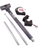
Min. Element Length: 2.6 inches [6.6 cm]
Max. Element Length: 114 inches [290 cm]
Isotropic Gain: 1.6 dBi
VSWR: less than 1.5:1
Specifications: ANSI, CISPR, EN, ETSI, etc.
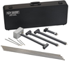
Weight 15 lbs. (6.8 kg) (including baluns, elements & case)
Adjustable (Tunable) Elements
Dipoles considered “reference antenna”
Rugged Carrying/Storage Case for transport and protected storage
Three-year Standard Warranty
The AD-100A is a Half-Wave Tuned Dipole Antenna Set, complete with custom carrying/storage case. The set includes the four standard antenna balans described in ANSI C63.5, along with all of the necessary antenna elements for the frequency range of 30 MHz to 1 GHz. This frequency range is divided into four subranges, corresponding to the frequency range of each individual balan.
Calibration
Per ANSI C63.4 & CISPR 16-1-4, no calibration of half-wave dipoles is required beyond verification of balun loss (<0.5 dB) and VSWR (<1.5:1). Antenna factors are instead determined by calculation.
For a theoretical “loss-less” half-wave dipole:
“Loss-less” Dipole Factor = 20*log(Freq. in MHz) - 31.9
In order to account for the loss of the balun:
Dipole Factor = 20*log(Freq. in MHz) - 31.9 + Balun Loss (dB)
Dipole Factor = 20*log(Freq. in MHz) - 31.9 + 0.5
NIST Traceable or 17025 Accredited Calibration of the AD-100 Tuned Dipole Set is, however, available upon request.
Application
Dipole antennas are considered to be the reference (or standard) antenna. They are still the preferred antennas for discrete frequency field strength measurements associated with Normalized Site Attenuation (NSA) calibrations of Open Area Test Sites (OATS) and Semi-Anechoic Chambers (SAC), and for most radiated electromagnetic interference (EMI) compliance tests. Also, they are the only type of antenna that is to be used for calibration of broadband antennas (such as biconical dipoles log periodic dipole arrays, etc.) when employing the reference antenna method described in ANSI C63.5: 2006.
Dipoles are also used as the “substitution antenna” for Effective Radiated Power (ERP) and/or Effective Isotropic Radiated Power (EIRP) tests of intentional radiators (RF transmitters).
Construction
The AD-100A Tuned Dipole Antenna Set is designed based on the Reference Antenna Example Drawings given in Appendix E of ANSI C63.5: 2006. As part of the manufacturing process, the insertion loss of each balun is verified to be less than 0.5 dB, and the VSWR less than 1.5:1 with the elements tuned to resonance at a low, middle and high end of each balun’s respective frequency range. The antennas are designed for durability using high quality materials. This makes the AD-100A set the ideal choice for use in laboratory environments.
The AD-100A is a 1 GHz dipole antenna from Com-Power. A state-of-the-art antenna preamplifier can enhance the performance of electronic test equipment with a bad or weak signal. Antennas boost signals and can overcome signal losses related to splitters and junctions.
Additional Features:
- Frequency Range: 30 MHz to 1 GHz
- Polarization: Linear
- Nominal Impedance: 50Ω
- RF Connectors: BNC-type (female)
- Min. Element Length: 2.6 inches [6.6 cm]
- Max. Element Length: 114 inches [290 cm]
- Isotropic Gain: 1.6 dBi
- VSWR: less than 1.5:1
- Specifications: ANSI, CISPR, EN, ETSI, etc.
- Weight 15 lbs. (6.8 kg) (including baluns, elements & case)
- Adjustable (Tunable) Elements
- Dipoles considered “reference antenna”
- Rugged Carrying/Storage Case for transport and protected storage
- Three-year Standard Warranty
The AD-100A is a Half-Wave Tuned Dipole Antenna Set, complete with custom carrying/storage case. The set includes the four standard antenna balans described in ANSI C63.5, along with all of the necessary antenna elements for the frequency range of 30 MHz to 1 GHz. This frequency range is divided into four subranges, corresponding to the frequency range of each individual balan.
Calibration
Per ANSI C63.4 & CISPR 16-1-4, no calibration of half-wave dipoles is required beyond verification of balun loss (<0.5 dB) and VSWR (<1.5:1). Antenna factors are instead determined by calculation.
For a theoretical “loss-less” half-wave dipole:
- “Loss-less” Dipole Factor = 20*log(Freq. in MHz) - 31.9
In order to account for the loss of the balun:
- Dipole Factor = 20*log(Freq. in MHz) - 31.9 + Balun Loss (dB)
- Dipole Factor = 20*log(Freq. in MHz) - 31.9 + 0.5
NIST Traceable or 17025 Accredited Calibration of the AD-100 Tuned Dipole Set is, however, available upon request.
Application
Dipole antennas are considered to be the reference (or standard) antenna. They are still the preferred antennas for discrete frequency field strength measurements associated with Normalized Site Attenuation (NSA) calibrations of Open Area Test Sites (OATS) and Semi-Anechoic Chambers (SAC), and for most radiated electromagnetic interference (EMI) compliance tests. Also, they are the only type of antenna that is to be used for calibration of broadband antennas (such as biconical dipoles log periodic dipole arrays, etc.) when employing the reference antenna method described in ANSI C63.5: 2006.
Dipoles are also used as the “substitution antenna” for Effective Radiated Power (ERP) and/or Effective Isotropic Radiated Power (EIRP) tests of intentional radiators (RF transmitters).
Construction
The AD-100A Tuned Dipole Antenna Set is designed based on the Reference Antenna Example Drawings given in Appendix E of ANSI C63.5: 2006. As part of the manufacturing process, the insertion loss of each balun is verified to be less than 0.5 dB, and the VSWR less than 1.5:1 with the elements tuned to resonance at a low, middle and high end of each balun’s respective frequency range. The antennas are designed for durability using high quality materials. This makes the AD-100A set the ideal choice for use in laboratory environments.