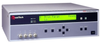
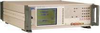
The 1910 is a 1 MHz LCR meter from QuadTech. An LCR meter is a piece of electronic test equipment that measures inductance (L), capacitance (C), and resistance (R) of electronic components. The LCR meter accurately measures these elements on an electronic device, usually one subjected to an alternating current (AC) voltage source. The LCR meter measures the current through and voltage across the device under test.
Additional Features:
20Hz to 1MHz Frequency Range
0.1% Basic Measurement Accuracy
Selectable source Impedence
Displays Voltage and Current Measurements
Wide Measurement Range with 5 Digit Measurement Resolution
Four-terminal Kelvin connections to maintain measurement integrity
1A DC Bias
PC Software Configurable
Multiple Steps
Sequence Testing up to six individual tests in one pass
Menu driven interface provides user friendly operation
Measurement auto ranging or manual hold
15 total bins
Measurement averaging from 1 to 1000
IEEE-488.2, RS-232, handler, and serial printer interfaces all standard
Display of DUT actual voltage
Display of DUT current
Load Correction
Specifications
Test Frequency
Range: 20Hz to 1MHz, Continuous
Resolution: 1Hz from 20Hz to 1KHz
4 digits >1KHz
Accuracy: +/- (0.01% +0.02 Hz)
Measurement Speed
Fast: 40 meas/sec
Medium: 8 meas/sec
Slow: 1 meas/sec
Ranging
Automatic, Range Hold or user selectable
Trigger
Internal (automatic)
External: Via RS-232, IEEE-488.2 or Handler interfaces
Manual
Source Impedance
5V, 25V, 50V, 100V, or matched impedance, range dependent
AC Test Signal
Voltage: 20mV to 1.0V (open circuit) in 5 mV steps
DC Bias Current
Internal: 0.0 to 1.0A in 1mA steps
External: 0.0 to 20.0A in 5mA steps using QuadTech 1320
Display
LCD Display with backlight
Results Formats
Engineering numeric format
% Deviation from nominal of primary parameter
Deviation from nominal of primary parameter
Pass/Fail
No Display Mode for maximum throughput
Sequencing:
Displays up to 6 sequential test results, primary and/or secondary
Standard Interfaces
IEEE-488.2 • RS-232 • Handler • Serial Printer
Measurement Delay
Programmable from 0 to 1000 ms in 1ms steps
Averaging
Programmable from 1 to 1000
Median Value
Averaged over last three measurements
Calibration
Recommended interval 1 year
NIST traceable calibration
Built-in automatic calibration procedure
Usage & Cal Data
Displays last calibration date, standard values used in calibration
Self Test
Verifies critical instrument operation at power-up or when selected from menu
Test Terminals
Front panel, four terminal (BNC)
Optional Test Fixtures Available
Mechanical
Bench mount with tilt bail
Rack mount kit optional
Dimensions: 17x 5.25x 16in (432x 133x 406 mm)
Enviromental
Meets MIL-T-28800E, Type3, Class 5, Style E & F
Operating 0° to +50°C
Humidity < 75% for 11° to 30°C operating
Storage -40° to +71° C
The 1910 Inductance Analyzer is designed to perform inductance and impedance measurements on coils and wire wound devices over a frequency range from 20Hz to 1MHz. Emphasis has been placed on ease of use through menu programming, and fast accurate production testing via its remote control capability
15 Different Impedance Parameters/20 Total Parameters
Measure and display any two parameters simutaneously, to achieve coverage and flexibility not previously available.
Automatic Test Sequencing
Run up to six different tests in sequence with a single push of the start button. Each test can have different conditions and limits.
Program and Data Storage
Test setups can be stored and recalled from internal memory. The front panel can be locked out, with password protection, to ensure procedures are run the same way every time.
Load Correction
Substantially improves instrument accuracy by performing measurements on a known standard and applying correction to subsequent measurements. Ideal for repetitive testing of identical devices at like test conditions.
The 1910 is a 1 MHz LCR meter from QuadTech. An LCR meter is a piece of electronic test equipment that measures inductance (L), capacitance (C), and resistance (R) of electronic components. The LCR meter accurately measures these elements on an electronic device, usually one subjected to an alternating current (AC) voltage source. The LCR meter measures the current through and voltage across the device under test.
Additional Features:
- 20Hz to 1MHz Frequency Range
- 0.1% Basic Measurement Accuracy
- Selectable source Impedence
- Displays Voltage and Current Measurements
- Wide Measurement Range with 5 Digit Measurement Resolution
- Four-terminal Kelvin connections to maintain measurement integrity
- 1A DC Bias
- PC Software Configurable
- Multiple Steps
- Sequence Testing up to six individual tests in one pass
- Menu driven interface provides user friendly operation
- Measurement auto ranging or manual hold
- 15 total bins
- Measurement averaging from 1 to 1000
- IEEE-488.2, RS-232, handler, and serial printer interfaces all standard
- Display of DUT actual voltage
- Display of DUT current
- Load Correction
Specifications
Test Frequency
- Range: 20Hz to 1MHz, Continuous
- Resolution: 1Hz from 20Hz to 1KHz
- 4 digits >1KHz
- Accuracy: +/- (0.01% +0.02 Hz)
Measurement Speed
- Fast: 40 meas/sec
- Medium: 8 meas/sec
- Slow: 1 meas/sec
Ranging
- Automatic, Range Hold or user selectable
Trigger
- Internal (automatic)
- External: Via RS-232, IEEE-488.2 or Handler interfaces
- Manual
Source Impedance
- 5V, 25V, 50V, 100V, or matched impedance, range dependent
AC Test Signal
- Voltage: 20mV to 1.0V (open circuit) in 5 mV steps
DC Bias Current
- Internal: 0.0 to 1.0A in 1mA steps
- External: 0.0 to 20.0A in 5mA steps using QuadTech 1320
Display
- LCD Display with backlight
Results Formats
- Engineering numeric format
- % Deviation from nominal of primary parameter
- Deviation from nominal of primary parameter
- Pass/Fail
- No Display Mode for maximum throughput
Sequencing:
- Displays up to 6 sequential test results, primary and/or secondary
Standard Interfaces
- IEEE-488.2 • RS-232 • Handler • Serial Printer
Measurement Delay
- Programmable from 0 to 1000 ms in 1ms steps
Averaging
- Programmable from 1 to 1000
Median Value
- Averaged over last three measurements
Calibration
- Recommended interval 1 year
- NIST traceable calibration
- Built-in automatic calibration procedure
Usage & Cal Data
- Displays last calibration date, standard values used in calibration
Self Test
- Verifies critical instrument operation at power-up or when selected from menu
Test Terminals
- Front panel, four terminal (BNC)
- Optional Test Fixtures Available
Mechanical
- Bench mount with tilt bail
- Rack mount kit optional
- Dimensions: 17x 5.25x 16in (432x 133x 406 mm)
Enviromental
- Meets MIL-T-28800E, Type3, Class 5, Style E & F
- Operating 0° to +50°C
- Humidity < 75% for 11° to 30°C operating
- Storage -40° to +71° C
The 1910 Inductance Analyzer is designed to perform inductance and impedance measurements on coils and wire wound devices over a frequency range from 20Hz to 1MHz. Emphasis has been placed on ease of use through menu programming, and fast accurate production testing via its remote control capability
15 Different Impedance Parameters/20 Total Parameters
Measure and display any two parameters simutaneously, to achieve coverage and flexibility not previously available.
Automatic Test Sequencing
Run up to six different tests in sequence with a single push of the start button. Each test can have different conditions and limits.
Program and Data Storage
Test setups can be stored and recalled from internal memory. The front panel can be locked out, with password protection, to ensure procedures are run the same way every time.
Load Correction
Substantially improves instrument accuracy by performing measurements on a known standard and applying correction to subsequent measurements. Ideal for repetitive testing of identical devices at like test conditions.