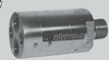

FEATURES: Hydraulic Intensifiers convert a given hydraulic pressure on the input side to a higher pressure on the output side. This allows using the comparatively low pressure of machine-tool hydraulics to pressurize a clamping fixture with several times that pressure. These pump units can be used for fixtures of any size, because clamps are initially charged by the lower input pressure, then build to final pressure as the oscillating pump automatically operates. Automatic pressure control is assured, because the pump automatically restarts if pressure drops.
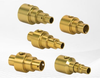
SIZES: Available in two versions, standard flow rate and high flow rate, each with a choice of several intensification ratios. Standard-flow-rate intensifiers are available with any of the following intensification ratios — see Dimensions page for part numbers:
3.2
4.0
4.8
6.2
7.5
High-flow-rate intensifiers are available with any of the following intensification ratios:
1.5
2.0
3.2
4.0
5.0
OPERATION: Fluid is supplied through input IN via the check valves RV1, RV2, and DV to the high-pressure output H and thereby to the cylinders. In this initial stage, the intensifier is in rapid low-pressure function with a high flow rate. With increasing pressure, the oscillating pump automatically functions (pulsation at 30 cycles/sec max). As soon as final pressure is attained, the pulsation stops (pulsation continues in case of dynamic applications). To retract the cylinders, the internal check valve DV is controlled via port R, and thereby free-flow return through the intensifier is guaranteed.
FLUID CONNECTION: Hydraulic fluid must be thoroughly filtered, with particles no larger than 10 microns nominal. To accomplish this, we offer an in-line filter unit (CLR-3887-064-V) that can be directly integrated into the tubing of the low-pressure side. Do not use NPT fittings.
DESIGN CONSIDERATIONS: If the intensifier will be used in an uncoupled system, a pilot-operated check valve should be installed on the high-pressure side. Please note, there is a slight leakage rate between the ports IN and R of the high-pressure side (leakage rate approximately 3 cu. in./min). When using the intensifier in an uncoupled system, there will be a pressure increase in the unclamping line due to the leakage rate – please contact factory for technical assistance.
| Carr Lane Manufacturing Co. | |
|---|---|
| Product Category | Pressure Intensifiers and Boosters |
| Product Number | CLR-8755-162-HI |
| Product Name | Hydraulic Intensifier |
| Technology Type | Hydraulic |
| Maximum Output Pressure | 7500 psi (5278 m H2O) |
| Pressure Intensification Factor | 6.2 |