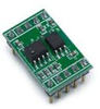
Broadcom Inc. ACPL-M61L/064L SPI Evaluation Board EVBD-ACPL-SPI

Description
The ACPL-M61L (single-channel in SO-5 footprint) and ACPL-064L (dual-channel in SO-8 footprint) are low power, low input current, 10 MBd digital optocouplers. They are designed to operate at VDD from 2.7 V to 5.5 V and IDD of 1.3 mA/ch max. The input LED can be driven with a low input driving current of 1.6 mA. The ACPL-M61/064L has a common mode transient immunity of 20 kV/μs (min.) at VCM = 1000 V. The ACPL-M61L/064L evaluation board allows designers to evaluate Avago digital optocouplers easily on a solder¬less breadboard. The evaluation board contains one ACPL-064L and one ACPL-M61L (orientated 180°) to provide a total of three channels (two in the forward direction and one in the reverse direction). This combination is well-suited for isolation of most bus interfaces comprising of clock and separate data in/out signals. Users may balance the input current limiting resistance between anode and cathode of each channel by replacing the dummy 0-ohm resistors on the evaluation board. This split resistor configuration improves the common mode rejection performance of the optocouplers. Applications Communication Interface: RS485, CANBus, I2C Microprocessor System Interfaces Digital isolation for A/D and D/A conversion

Suppliers

Company
Product
Description
Supplier Links
ACPL-M61L/064L SPI Evaluation Board - EVBD-ACPL-SPI - Broadcom Inc.
San Jose, CA, USA
ACPL-M61L/064L SPI Evaluation Board
EVBD-ACPL-SPI
ACPL-M61L/064L SPI Evaluation Board EVBD-ACPL-SPI
The ACPL-M61L (single-channel in SO-5 footprint) and ACPL-064L (dual-channel in SO-8 footprint) are low power, low input current, 10 MBd digital optocouplers. They are designed to operate at VDD from 2.7 V to 5.5 V and IDD of 1.3 mA/ch max. The input LED can be driven with a low input driving current of 1.6 mA. The ACPL-M61/064L has a common mode transient immunity of 20 kV/μs (min.) at VCM = 1000 V. The ACPL-M61L/064L evaluation board allows designers to evaluate Avago digital optocouplers easily on a solder¬less breadboard. The evaluation board contains one ACPL-064L and one ACPL-M61L (orientated 180°) to provide a total of three channels (two in the forward direction and one in the reverse direction). This combination is well-suited for isolation of most bus interfaces comprising of clock and separate data in/out signals. Users may balance the input current limiting resistance between anode and cathode of each channel by replacing the dummy 0-ohm resistors on the evaluation board. This split resistor configuration improves the common mode rejection performance of the optocouplers. Applications Communication Interface: RS485, CANBus, I2C Microprocessor System Interfaces Digital isolation for A/D and D/A conversion

The ACPL-M61L (single-channel in SO-5 footprint) and ACPL-064L (dual-channel in SO-8 footprint) are low power, low input current, 10 MBd digital optocouplers. They are designed to operate at VDD from 2.7 V to 5.5 V and IDD of 1.3 mA/ch max. The input LED can be driven with a low input driving current of 1.6 mA.
The ACPL-M61/064L has a common mode transient immunity of 20 kV/μs (min.) at VCM = 1000 V.
The ACPL-M61L/064L evaluation board allows designers to evaluate Avago digital optocouplers easily on a solder¬less breadboard. The evaluation board contains one ACPL-064L and one ACPL-M61L (orientated 180°) to provide a total of three channels (two in the forward direction and one in the reverse direction). This combination is well-suited for isolation of most bus interfaces comprising of clock and separate data in/out signals.
Users may balance the input current limiting resistance between anode and cathode of each channel by replacing the dummy 0-ohm resistors on the evaluation board. This split resistor configuration improves the common mode rejection performance of the optocouplers.

Applications

  • Communication Interface: RS485, CANBus, I2C
  • Microprocessor System Interfaces
  • Digital isolation for A/D and D/A conversion
Supplier's Site

Technical Specifications

  Broadcom Inc.
Product Category Electronic Development Boards
Product Number EVBD-ACPL-SPI
Product Name ACPL-M61L/064L SPI Evaluation Board
Category Developement Board
Unlock Full Specs
to access all available technical data

Similar Products

Evaluation and Demonstration Boards and Kits - 2952-MP.PD1.JSM.2.33-ND - DigiKey
Innovative Sensor Technology IST USA Division
Specs
Category Developement Board
Supported System Special Purpose
View Details
2 suppliers
LED Development Tools - 1887086 - RS Components, Ltd.
Specs
Category Development Suite / Kit
View Details
TB,MNA-6W+,DQ849,08AM02,50 OHM - TB-186-6W+ - Mini-Circuits
Specs
Category Developement Board
View Details
simpleRTK3B Heading - AS-RTK3B-MH-L1L2-NH-01 - ArduSimple
Specs
Category Developement Board
Supported System Communications/Networking
View Details