GarrettCom, Inc.E1 to T1 Rate and Interface ConverterSPD-E1
Description
FEATURES
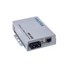
The SPD-E1 Rate and Interface Converter enables E1 equipment to utilize two T1 transmission links, by converting any E1 frame (2.048 Mbps) into two T1 frames(1.544 Mbps). SPD-E1 is transparent to the E1 framing pattern.
Jitter attenuation on each side guarantees smooth, jitter-free operation.
T1 parameters include D4 or ESF framing and AMI or B8ZS codes. In the ESF format, T1 main link statistics are stored in memory, in compliance with both ANSI and AT&T standards, and may be retrieved by the service supplier, or by the user via the supervisory port.
Timing options cover all timing situations. These include:
Transparent timing: T1 transmit clock of both links is locked to E1 receive clock, and E1 transmit clock is locked to T1-A receive clock.
Loopback timing: T1 transmit clock for both links is derived from T1-A receive clock. E1 transmit clock is derived from E1 receive clock.
Internal clock: Internal oscillator is the source for both E1 and T1 transmit clocks.
Station clock: The source for both the E1 and T1 transmit clocks is the framed/unframed all "1"s T1 (AMI).
Independent elastic buffering in each direction compensates for short term deviations in timing sources. Buffer size is 16 E1 frames ( 4096 bits).
The E1 frame (256 bits) is equally divided between both T1 frames, utilizing timeslots 1 to 16 of each T1 link. Spare bandwidth may accommodate an additional DTE data channel.
Data rates for the data channel are selectable for any multiple of 56 or 64 kbps, up to 1024 kbps. The DTE channel interface is available as V.35 or RS-530/RS-422.
Setup, control and monitoring of status and diagnostic information can be performed via an ASCII terminal. Setup of the basic unit can also be performed via internal jumpers. Automatic dial-up is also supported whenever an alarm event occurs.
Diagnostic loopbacks, activated either from the front panel or from the ASCII terminal, include:
E1 loopback towards the local DTE;
T1 loopback on both links, towards the remote DTE;
T1 network line loopback with carrier code activated on each T1 link.
SPD-E1 is available as a desktop unit, with rack mount hardware for mounting in a 19' rack.
Data Connect Enterprise, Inc.
Done
Description
FEATURES
The SPD-E1 Rate and Interface Converter enables E1 equipment to utilize two T1 transmission links, by converting any E1 frame (2.048 Mbps) into two T1 frames(1.544 Mbps). SPD-E1 is transparent to the E1 framing pattern.
Jitter attenuation on each side guarantees smooth, jitter-free operation.
T1 parameters include D4 or ESF framing and AMI or B8ZS codes. In the ESF format, T1 main link statistics are stored in memory, in compliance with both ANSI and AT&T standards, and may be retrieved by the service supplier, or by the user via the supervisory port.
Timing options cover all timing situations. These include:
Transparent timing: T1 transmit clock of both links is locked to E1 receive clock, and E1 transmit clock is locked to T1-A receive clock.
Loopback timing: T1 transmit clock for both links is derived from T1-A receive clock. E1 transmit clock is derived from E1 receive clock.
Internal clock: Internal oscillator is the source for both E1 and T1 transmit clocks.
Station clock: The source for both the E1 and T1 transmit clocks is the framed/unframed all "1"s T1 (AMI).
Independent elastic buffering in each direction compensates for short term deviations in timing sources. Buffer size is 16 E1 frames ( 4096 bits).
The E1 frame (256 bits) is equally divided between both T1 frames, utilizing timeslots 1 to 16 of each T1 link. Spare bandwidth may accommodate an additional DTE data channel.
Data rates for the data channel are selectable for any multiple of 56 or 64 kbps, up to 1024 kbps. The DTE channel interface is available as V.35 or RS-530/RS-422.
Setup, control and monitoring of status and diagnostic information can be performed via an ASCII terminal. Setup of the basic unit can also be performed via internal jumpers. Automatic dial-up is also supported whenever an alarm event occurs.
Diagnostic loopbacks, activated either from the front panel or from the ASCII terminal, include:
E1 loopback towards the local DTE;
T1 loopback on both links, towards the remote DTE;
T1 network line loopback with carrier code activated on each T1 link.
SPD-E1 is available as a desktop unit, with rack mount hardware for mounting in a 19' rack.