The 5335B is a power analyzer from BK Precision. A power analyzer, or power quality analyzer, can take accurate measurements of direct current DC, alternating current AC, voltages, phase rotations, and power in many different types of electronic equipment. Engineers can test power supplies, industrial machinery, motor drivers, home appliances, and office equipment with used and refurbished power analyzers.
Additional Features:
600 Vrms (Cat II) and 20 Arms direct input ranges
Frequency ranges DC, 0.5 Hz to 100 kHz
0.1% basic accuracy for voltage and current measurements
4.3-inch color LCD (TFT)
Simultaneously measure and display up to 12 measurement parameters
Capture inrush current, and voltage surge with the peak function
Harmonic measurements to the 50th order
Integration function with automatic range switching
Ability to measure electrical energy which is produced or consumed
Pre-compliance testing according to IEC/EN 62000-3-2/4-7
Standard USB, GPIB, RS232 and LAN interfaces
Line and frequency filter capability for reducing unwanted signal noise
Optional universal breakout box to simplify connection between power meter and DUT
Applications
Measure power, electrical energy bought or sold back to the power grid, inverters, harmonics of motors, un-interruptible power supplies, appliances, and consumer electronics
General Measurement Specifications
Specifications are subject to the following conditions:
Temperature: 23±5° C, humidity: 30 to 75% RH.
Warm-up time: 30 minutes
Basic measurements
Voltage, Current: Peak to peak, Maximum, Minimum, Average_rms, Average_rectified, DC, Crest factor (current), Inrush (current)
Power: Real, Apparent, Reactive, DC, Power factor
Time: Frequency, Phase
Integration: Total power, Total current, Maximum power, Minimum power
Harmonic measurements
Type: Current, Voltage, Real power, Apparent power, Reactive power, Power factor, Phase, Percentage of total (Current, Voltage, Power)
Range: DC up to 50th order
Max. Frequency: 100 kHz
Input bandwidth: DC, 0.5 Hz to 100 kHz
Measurement method: Digital sampling
A/D Converter: Simultaneous conversion of voltage and current inputs, Resolution: 18-bit, Maximum conversion rate: 10 μs
Line filter: Select OFF or ON (cutoff frequency at 500 Hz)
Peak (max, min): Voltage, current, or power
Input voltage continuous max.: 1.5 kV-peak or 1 kV-RMS, whichever is less
Input voltage transient (<1s) max.: 2 kV-peak or 1.5 kV-RMS, whichever is less
Input voltage common-mode max.: 600 Vrms
Voltage input impedance: 2 Mω + 13 pF in parallel (typical)
Current input impedance (typical): 5 mA to 200 mA range: 505 mω + 0.1 μH; 0.5 A to 20 A range: 5 mω + 0.1 μH; Sensor input: 20 kω (50 mV to 2 V); 100 kω (2.5 V to 10 V)
Input current continuous max: 5 mA to 200 mA range: 30 A-peak or 20 A-RMS, whichever is less; 0.5 A to 20 A range: 100 A-peak or 30 A-RMS, whichever is less; Sensor input: Peak value less than or equal to 5 times the rated range
Input current transient (<1s) max.: 5 mA to 200 mA range: 30 A-peak or 20 A-RMS, whichever is less; 0.5 A to 20 A range: 150 A-peak or 40 A-RMS, whichever is less; Sensor input: Peak value less than or equal to 10 times the rated range
Voltage Measurement Accuracy and Ranges
Ranges: CF=3: 15 V, 30 V, 60 V, 150 V, 300 V, 600 V; CF=6: 7.5 V, 15 V, 30 V, 75 V, 150 V, 300 V
Accuracy (line, frequency, & digital filter set to off)
DC - 1 kHz: ± (0.1% + 0.2% F.S.)
1 kHz < f ≤ 10 kHz: ± ((0.07 f1 ) % + 0.3% F.S.)
10 kHz < f ≤ 100 kHz: ± (0.5% + 0.5% F.S.) ± [{0.04 × (f1-10)} % ]
Temperature coefficient
For temperature changes after zero-level compensation or range change: + 0.02% F.S. /°C to the DC voltage accuracy
Influence of self-generated heat caused by voltage input (U is the voltage reading (V)): + 0.0000001 × U2 % to the AC voltage accuracy; + 0.0000001 × U2 % + 0.0000001 × U2 % F.S. to DC current accuracy
Current Measurement Accuracy and Ranges
Direct input range
CF= 3:5 mA, 10 mA, 20 mA, 50 mA, 100 mA, 200 mA, 0.5 A, 1 A, 2 A, 5 A, 10 A, 20 A; CF= 6:2.5 mA, 5 mA, 10 mA, 25 mA, 50 mA, 100 mA, 250 mA, 0.5 A, 1 A, 2.5 A, 5 A, 10 A
Sensor input range
External 1: CF = 3: 2.5 V, 5 V, 10 V; CF = 6: 1.25 V, 2.5 V, 5 V
External 2: CF= 3: 50 mV, 100 mV, 200 mV, 500 mV, 1 V, 2 V; CF= 6: 25 mV, 50 mV, 100 mV, 250 mV, 500 mV, 1 V
Accuracy (line, frequency, & digital filter set to off)
DC to 1 kHz: ± (0.1% + 0.2% F.S.)
1 kHz < f ≤ 10 kHz: ± {(0.07 f1)% + 0.3% F.S.}
10 kHz < f ≤ 100 kHz: ± (0.5% + 0.5% F.S.) ± [{0.04×(f1-10)}%]
Temperature coefficient
2.5 to 200 mA: 5 µA/ °C (after zero-level compensation, or range change)
500 mA to 20 A: 500 µA/ °C (after zero-level compensation, or range change)
Influence of internal sensor self-heating: + 0.00013 × I % of reading to the AC current accuracies + 0.00013 × I% of reading + 0.004 × I mA (0.5 to 20 A) or 0.00013 × I% of reading + 0.00004 × I mA (2.5 to 200 mA), add to the DC current accuracy specifications
Power Measurement Accuracy
Real power accuracy (CF= 3)
DC: ± (0.1% + 0.2% F.S.)
0.5 Hz ≤ f < 45 Hz: ± (0.3% + 0.2% F.S.)
45 Hz ≤ f ≤ 66 Hz: ± (0.1% + 0.1% F.S.)
66 Hz < f ≤ 1 kHz: ± (0.2% + 0.2% F.S.)
1 kHz < f ≤ 10 kHz: ± (0.1% + 0.3% F.S.) ± [{0.067×(f-1)}%]
10 kHz < f ≤ 100 kHz: ± (0.5% + 0.5% F.S.) ± [{0.09×(f-10)}%]
Apparent power (S): Voltage accuracy + current accuracy
Reactive power (Q): Apparent power accuracy + (1.0004-PF2) - (1-PF2) × 100%
Power factor (PF): ±[(PF–PF/1.0002) + abs (cosø - cos{ø+sin-1(influenc
e from the power factor when PF=0%/100)})] ± 1 digit when voltage and current are at the measurement range rated input
Phase difference (?): ± [abs(ø - cos-1(PF/1.0002)) + sin-1{(influence from the power factor when PF=0%)/100}] deg ± 1 digit when voltage and current are at the measurement range rated input
Temperature coefficient: Same as the temperature coefficient for voltage and current
Frequency Measurement Accuracy
Accuracy: ±0.06%: (CF 3 and signal <30% F.S.) or, (CF 6 and signal <60% F.S.), and ≤ 200 Hz with frequency filter on
Frequency filter: 500 Hz low-pass
Harmonic Measurement Parameters
Measurement method: PLL synchronization
Frequency range: PLL frequency source range 10 Hz to 1.2 kHz (typical)
FFT data length: 1024
Window function: Rectangle
Oscilloscope Function
Channels: 2
Measurement: Voltage and current
Bandwidth (-3 dB): 10 kHz
Sample rate: 100 kS/s
Record length: 300 points/channel
Horizontal scale (Accuracy ±4.0%): 500 us, 1 ms, 2 ms, 5 ms, 10 ms, 20 ms, 50 ms, 100 ms, 200 ms, 500 ms
Vertical scale ranges (Accuracy ±4.0%): CF 3: I: 2.5, 5, 10, 25, 50, 100, 250, 500 mA/div, 1 A, 2.5 A, 5 A, 10 A/div,; U: 7.5, 15, 30, 75, 150, 300 V/div; CF 6: I: 5, 10, 20, 50, 100, 200, 500 mA/div, 1 A, 2 A, 5 A, 10 A, 20 A/div,; U: 15, 30, 60, 150, 300, 600 V/div
Maximum input voltage (DC+AC peak): 1800 V
Maximum input current (DC+AC peak): 60 A
Environmental and Safety
Temperature: Operating: 41 ºF to 104 ºF (5 °C to 40 °C); Storage: -4 ºF to 122 ºF (-20 °C to 50 °C)
Humidity: 20% RH to 80% RH (non-condensing)
Electromagnetic compatibility: IEC 61326
Safety: IEC 61010-1, EN 61010-1, Measurement 600 V CAT II
General
Display: 4.3” TFT-LCD display, 480 x 272
Remote Interfaces: USB, GPIB, RS232, LAN
Power: 100 to 240 VAC, 50 / 60 Hz
Power Consumption 50 VA max.
Dimensions (W x H x D): 8.4” x 3.5” x 14” (214.5 × 88.2 × 354.6 mm)
Three-Year Warranty
Standard Accessories: Getting started manual, instruction manual (downloadable), AC power cord, USB type A-to-type B cable, certificate of calibration
Optional Accessories: Power Cord Breakout Box (TLBB53)
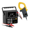
The 5335B is a compact, single-phase AC / DC power meter for measuring and analyzing power consumption and power quality parameters quickly and accurately. It supports power measurements up to 600 Vrms, and 20 Arms, with a bandwidth up to of 100 kHz.
Rich Measurement Functions
Measure all AC and DC parameters, including power, current, voltage, power factor, frequency, and phase.
Additionally, the meter features a powerful integration function, the ability to perform harmonic measurements to the 50th order and an oscilloscope mode for viewing voltage and current readings in the time domain.
Intuitive user interface
The large 4.3 inch color LCD screen enables easy viewing of configuration and measurements. Use the dedicated function keys to select one of the 4 main measurement modes: meter, harmonic, integral or oscilloscope. The results are displayed in numeric and graphical format. Screenshots can be saved directly to a USB flash drive.
Flexible operation
Harmonic measurement
Voltage, current, active power, reactive power and phase values of each harmonic can be measured and displayed as a list or bar chart, enabling the user to quickly visualize and analyze the results. Total harmonic distortion (THD) can be evaluated up to the 50th order with the ability to display individual harmonic components.
Integration measurement
The integration function is useful for analyzing bought and sold electrical energy of a grid tied power systems. The 5335B meter provides current integral and active power integral (Wh) functionality using automatic range switching for accurate measurement results.
Current sensor input
Current measurements above 20 A are supported by connecting an external current sensor to the external sensor interface.
To accommodate commonly available current sensor types, users can select from the 50 mV - 2 V or 2.5 V - 10 V ranges.
Motor testing
Many industrial products use PWM as a speed control method. The 5335B is able to measure input signals ranging from 0.5 Hz - 100 kHz and input voltages up to 600 V. Current can be monitored directly or by using external industry standard sensors.
Oscilloscope function
Displays waveforms of sampled voltage and current.
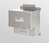
Optional universal breakout box
The optional TLBB53 breakout box simplifies AC line connection between the power meter and the DUT, and eliminates the need to cut the power cord and strip wires to connect to the power meter. This breakout box supports easy plug in connection and uses a universal socket to support most plugs used worldwide. A circuit breaker/ switch is also provided for additional protection.
The 5335B is a power analyzer from BK Precision. A power analyzer, or power quality analyzer, can take accurate measurements of direct current DC, alternating current AC, voltages, phase rotations, and power in many different types of electronic equipment. Engineers can test power supplies, industrial machinery, motor drivers, home appliances, and office equipment with used and refurbished power analyzers.
Additional Features:
- 600 Vrms (Cat II) and 20 Arms direct input ranges
- Frequency ranges DC, 0.5 Hz to 100 kHz
- 0.1% basic accuracy for voltage and current measurements
- 4.3-inch color LCD (TFT)
- Simultaneously measure and display up to 12 measurement parameters
- Capture inrush current, and voltage surge with the peak function
- Harmonic measurements to the 50th order
- Integration function with automatic range switching
- Ability to measure electrical energy which is produced or consumed
- Pre-compliance testing according to IEC/EN 62000-3-2/4-7
- Standard USB, GPIB, RS232 and LAN interfaces
- Line and frequency filter capability for reducing unwanted signal noise
- Optional universal breakout box to simplify connection between power meter and DUT
Applications
- Measure power, electrical energy bought or sold back to the power grid, inverters, harmonics of motors, un-interruptible power supplies, appliances, and consumer electronics
General Measurement Specifications
Specifications are subject to the following conditions:
- Temperature: 23±5° C, humidity: 30 to 75% RH.
- Warm-up time: 30 minutes
Basic measurements
- Voltage, Current: Peak to peak, Maximum, Minimum, Average_rms, Average_rectified, DC, Crest factor (current), Inrush (current)
- Power: Real, Apparent, Reactive, DC, Power factor
- Time: Frequency, Phase
- Integration: Total power, Total current, Maximum power, Minimum power
Harmonic measurements
- Type: Current, Voltage, Real power, Apparent power, Reactive power, Power factor, Phase, Percentage of total (Current, Voltage, Power)
- Range: DC up to 50th order
- Max. Frequency: 100 kHz
- Input bandwidth: DC, 0.5 Hz to 100 kHz
- Measurement method: Digital sampling
- A/D Converter: Simultaneous conversion of voltage and current inputs, Resolution: 18-bit, Maximum conversion rate: 10 μs
- Line filter: Select OFF or ON (cutoff frequency at 500 Hz)
- Peak (max, min): Voltage, current, or power
- Input voltage continuous max.: 1.5 kV-peak or 1 kV-RMS, whichever is less
- Input voltage transient (<1s) max.: 2 kV-peak or 1.5 kV-RMS, whichever is less
- Input voltage common-mode max.: 600 Vrms
- Voltage input impedance: 2 MΩ + 13 pF in parallel (typical)
- Current input impedance (typical): 5 mA to 200 mA range: 505 mΩ + 0.1 μH; 0.5 A to 20 A range: 5 mΩ + 0.1 μH; Sensor input: 20 kΩ (50 mV to 2 V); 100 kΩ (2.5 V to 10 V)
- Input current continuous max: 5 mA to 200 mA range: 30 A-peak or 20 A-RMS, whichever is less; 0.5 A to 20 A range: 100 A-peak or 30 A-RMS, whichever is less; Sensor input: Peak value less than or equal to 5 times the rated range
- Input current transient (<1s) max.: 5 mA to 200 mA range: 30 A-peak or 20 A-RMS, whichever is less; 0.5 A to 20 A range: 150 A-peak or 40 A-RMS, whichever is less; Sensor input: Peak value less than or equal to 10 times the rated range
Voltage Measurement Accuracy and Ranges
- Ranges: CF=3: 15 V, 30 V, 60 V, 150 V, 300 V, 600 V; CF=6: 7.5 V, 15 V, 30 V, 75 V, 150 V, 300 V
Accuracy (line, frequency, & digital filter set to off)
- DC - 1 kHz: ± (0.1% + 0.2% F.S.)
- 1 kHz < f ≤ 10 kHz: ± ((0.07 f1 ) % + 0.3% F.S.)
- 10 kHz < f ≤ 100 kHz: ± (0.5% + 0.5% F.S.) ± [{0.04 × (f1-10)} % ]
Temperature coefficient
- For temperature changes after zero-level compensation or range change: + 0.02% F.S. /°C to the DC voltage accuracy
- Influence of self-generated heat caused by voltage input (U is the voltage reading (V)): + 0.0000001 × U2 % to the AC voltage accuracy; + 0.0000001 × U2 % + 0.0000001 × U2 % F.S. to DC current accuracy
Current Measurement Accuracy and Ranges
Direct input range
- CF= 3:5 mA, 10 mA, 20 mA, 50 mA, 100 mA, 200 mA, 0.5 A, 1 A, 2 A, 5 A, 10 A, 20 A; CF= 6:2.5 mA, 5 mA, 10 mA, 25 mA, 50 mA, 100 mA, 250 mA, 0.5 A, 1 A, 2.5 A, 5 A, 10 A
Sensor input range
- External 1: CF = 3: 2.5 V, 5 V, 10 V; CF = 6: 1.25 V, 2.5 V, 5 V
- External 2: CF= 3: 50 mV, 100 mV, 200 mV, 500 mV, 1 V, 2 V; CF= 6: 25 mV, 50 mV, 100 mV, 250 mV, 500 mV, 1 V
Accuracy (line, frequency, & digital filter set to off)
- DC to 1 kHz: ± (0.1% + 0.2% F.S.)
- 1 kHz < f ≤ 10 kHz: ± {(0.07 f1)% + 0.3% F.S.}
- 10 kHz < f ≤ 100 kHz: ± (0.5% + 0.5% F.S.) ± [{0.04×(f1-10)}%]
Temperature coefficient
- 2.5 to 200 mA: 5 µA/ °C (after zero-level compensation, or range change)
- 500 mA to 20 A: 500 µA/ °C (after zero-level compensation, or range change)
- Influence of internal sensor self-heating: + 0.00013 × I % of reading to the AC current accuracies + 0.00013 × I% of reading + 0.004 × I mA (0.5 to 20 A) or 0.00013 × I% of reading + 0.00004 × I mA (2.5 to 200 mA), add to the DC current accuracy specifications
Power Measurement Accuracy
Real power accuracy (CF= 3)
- DC: ± (0.1% + 0.2% F.S.)
- 0.5 Hz ≤ f < 45 Hz: ± (0.3% + 0.2% F.S.)
- 45 Hz ≤ f ≤ 66 Hz: ± (0.1% + 0.1% F.S.)
- 66 Hz < f ≤ 1 kHz: ± (0.2% + 0.2% F.S.)
- 1 kHz < f ≤ 10 kHz: ± (0.1% + 0.3% F.S.) ± [{0.067×(f-1)}%]
- 10 kHz < f ≤ 100 kHz: ± (0.5% + 0.5% F.S.) ± [{0.09×(f-10)}%]
- Apparent power (S): Voltage accuracy + current accuracy
- Reactive power (Q): Apparent power accuracy + (1.0004-PF2) - (1-PF2) × 100%
- Power factor (PF): ±[(PF–PF/1.0002) + abs (cosØ - cos{Ø+sin-1(influence from the power factor when PF=0%/100)})] ± 1 digit when voltage and current are at the measurement range rated input
- Phase difference (?): ± [abs(Ø - cos-1(PF/1.0002)) + sin-1{(influence from the power factor when PF=0%)/100}] deg ± 1 digit when voltage and current are at the measurement range rated input
- Temperature coefficient: Same as the temperature coefficient for voltage and current
Frequency Measurement Accuracy
- Accuracy: ±0.06%: (CF 3 and signal <30% F.S.) or, (CF 6 and signal <60% F.S.), and ≤ 200 Hz with frequency filter on
- Frequency filter: 500 Hz low-pass
Harmonic Measurement Parameters
- Measurement method: PLL synchronization
- Frequency range: PLL frequency source range 10 Hz to 1.2 kHz (typical)
- FFT data length: 1024
- Window function: Rectangle
Oscilloscope Function
- Channels: 2
- Measurement: Voltage and current
- Bandwidth (-3 dB): 10 kHz
- Sample rate: 100 kS/s
- Record length: 300 points/channel
- Horizontal scale (Accuracy ±4.0%): 500 us, 1 ms, 2 ms, 5 ms, 10 ms, 20 ms, 50 ms, 100 ms, 200 ms, 500 ms
- Vertical scale ranges (Accuracy ±4.0%): CF 3: I: 2.5, 5, 10, 25, 50, 100, 250, 500 mA/div, 1 A, 2.5 A, 5 A, 10 A/div,; U: 7.5, 15, 30, 75, 150, 300 V/div; CF 6: I: 5, 10, 20, 50, 100, 200, 500 mA/div, 1 A, 2 A, 5 A, 10 A, 20 A/div,; U: 15, 30, 60, 150, 300, 600 V/div
- Maximum input voltage (DC+AC peak): 1800 V
- Maximum input current (DC+AC peak): 60 A
Environmental and Safety
- Temperature: Operating: 41 ºF to 104 ºF (5 °C to 40 °C); Storage: -4 ºF to 122 ºF (-20 °C to 50 °C)
- Humidity: 20% RH to 80% RH (non-condensing)
- Electromagnetic compatibility: IEC 61326
- Safety: IEC 61010-1, EN 61010-1, Measurement 600 V CAT II
General
- Display: 4.3” TFT-LCD display, 480 x 272
- Remote Interfaces: USB, GPIB, RS232, LAN
- Power: 100 to 240 VAC, 50 / 60 Hz
- Power Consumption 50 VA max.
- Dimensions (W x H x D): 8.4” x 3.5” x 14” (214.5 × 88.2 × 354.6 mm)
- Three-Year Warranty
- Standard Accessories: Getting started manual, instruction manual (downloadable), AC power cord, USB type A-to-type B cable, certificate of calibration
- Optional Accessories: Power Cord Breakout Box (TLBB53)
The 5335B is a compact, single-phase AC / DC power meter for measuring and analyzing power consumption and power quality parameters quickly and accurately. It supports power measurements up to 600 Vrms, and 20 Arms, with a bandwidth up to of 100 kHz.
Rich Measurement Functions
Measure all AC and DC parameters, including power, current, voltage, power factor, frequency, and phase.
Additionally, the meter features a powerful integration function, the ability to perform harmonic measurements to the 50th order and an oscilloscope mode for viewing voltage and current readings in the time domain.
Intuitive user interface
The large 4.3 inch color LCD screen enables easy viewing of configuration and measurements. Use the dedicated function keys to select one of the 4 main measurement modes: meter, harmonic, integral or oscilloscope. The results are displayed in numeric and graphical format. Screenshots can be saved directly to a USB flash drive.
Flexible operation
Harmonic measurement
Voltage, current, active power, reactive power and phase values of each harmonic can be measured and displayed as a list or bar chart, enabling the user to quickly visualize and analyze the results. Total harmonic distortion (THD) can be evaluated up to the 50th order with the ability to display individual harmonic components.
Integration measurement
The integration function is useful for analyzing bought and sold electrical energy of a grid tied power systems. The 5335B meter provides current integral and active power integral (Wh) functionality using automatic range switching for accurate measurement results.
Current sensor input
Current measurements above 20 A are supported by connecting an external current sensor to the external sensor interface.
To accommodate commonly available current sensor types, users can select from the 50 mV - 2 V or 2.5 V - 10 V ranges.
Motor testing
Many industrial products use PWM as a speed control method. The 5335B is able to measure input signals ranging from 0.5 Hz - 100 kHz and input voltages up to 600 V. Current can be monitored directly or by using external industry standard sensors.
Oscilloscope function
Displays waveforms of sampled voltage and current.
Optional universal breakout box
The optional TLBB53 breakout box simplifies AC line connection between the power meter and the DUT, and eliminates the need to cut the power cord and strip wires to connect to the power meter. This breakout box supports easy plug in connection and uses a universal socket to support most plugs used worldwide. A circuit breaker/ switch is also provided for additional protection.