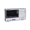
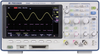
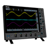
The 2544C is a 200 MHz, 2 Channel digital oscilloscope from BK Precision. Digital oscilloscopes make use of binary numbers that correspond to samples of the electronic equipment’s voltage. This is in contrast to analog oscilloscopes, which use continually varying voltages. Digital oscilloscopes use an analog-to-digital converter (ADC) to convert the voltages it measures into digital information
Additional Features:
1 GSa/s sample rate
14 Mpts maximum record length
16 digital channels with logic analyzer (MSO upgrade)
Serial bus decoding supporting I²C, SPI, UART/RS232, CAN, and LIN protocols (Decode upgrade)
Built-in Function and Arbitrary Waveform Generator comes standard on all models
Large 8” widescreen display with 256-level color gradient
60,000 wfms/s maximum waveform capture rate
Compact footprint and lightweight
High speed hardware-based pass/fail testing function and masking
Segmented acquisition history waveform record function (record length up to 80,000 frames)
Trigger types: Edge, Slope, Pulse, Video, Window, Runt, Interval, Dropout, Pattern, Serial
FFT including seven other math functions: Addition, Subtraction, Multiplication, Division, Integration, Differential, and Square Root
36 automatic measurements supporting statistics, gating, math, history and reference measurements
Multi-language user interface and built-in context sensitive help
Software provided for remote PC control
Front panel USB port for saving and recalling waveforms, setups, and screenshots
Standard LAN and USBTMC-compliant USB device port
Selectable 50ω and 1 Mω input coupling
Included Accessories: Passive probes (one per channel), power cord, certificate of calibration, USB (Type A to B) communication cable
Optional Accessories: 16-channel digital logic probe (LP2540C)
Three-Year Warranty
Performance Characteristics
Bandwidth: 200 MHz
Rise Time: <5 ns / <3.5 ns / <1.8 ns
Sample Rate: 1 GSa/s (single channel), 500 MSa/s (dual channel)
Input Channels Analog: 2
Digital: 16 (-MSO models or with LA2540C upgrade)
Memory Depth: 14 Mpts (single channel), 7 Mpts (dual channel)
Waveform Update Rate: 60,000 wfms/s
Hardware Bandwidth Limits: 20 MHz
Input Coupling: DC, AC, GND
Input Impedance: 1 M ω ± 2% || (22 pF ±3 pF); 50 ω ± 2%
Ch to Ch Isolation: >40dB
Acquisition System
Peak Detect: 1 ns
Average: 4, 16, 32, 64, 128, 256, 512, 1024
Enhanced Resolution: 0.5, 1, 1.5, 2., 2.5, 3 bits selectable
Interpolation: Sin(x)/x, Linear
Vertical System
Vertical Resolution: 8 bits
Vertical Sensitivity: 500 µV/div to 10 V/div (1-2-5)
Maximum Input Voltage: 1 M ω < 400 Vpk; 50 ω <5 Vrms
DC Gain Accuracy: ±3%: 5 mV/div to 10 V/div; ±4%: < 2 mV/div
Horizontal System
Time Base Range: 2.0 ns/div to 50 s/div
Time Base Accuracy: ±25 ppm
Ch to Ch Deskew Range: ±100 ns
Trigger System
Modes: Auto, Normal, Single
Coupling: DC, AC, LF Reject, HF Reject, Noise Reject Ch1-Ch2
Trigger Level: Internal: ±4.5 div from center; External: EXT: ±0.6 V; EXT/5: ±3 V
Hold-Off Range: 100 ns to 1.5 s
Types: Edge, Slope, Pulse, Video, Window, Interval, Dropout, Runt, Pattern
Serial Trigger: I²C, SPI, UART/RS232, CAN, LIN
Cursors
Mode: Manual, Track
Measurements: δT, 1/δT, X2, X1, δV, Y2, Y1
Waveform Math
Math Operation: Add, Subtract, Multiply, Divide, FFT, Derivative, Integral, Square Root
FFT: Windows: Rectangle, Blackman, Hanning, Hamming, Flattop
Waveform Measurements
Voltage: Vpp, Vmax, Vmin, Vamp, Vtop, Vbase, Mean, Cmean, Stdev, Cstd, Vrms, Crms, FOV, FPRE, ROV, RPRE, Level@Trigger
Time: +SR, -SR, Period, Freq, +Width, -Width, Rise, Fall, BWidth, +Duty, -Duty, Time@Mid
Delay: Phase, FRR, FRF, FFR, FFF, LRR, LRF, LFF, Skew
Statistics: Current, Mean, Min, Max, Stdev, Count
Gating: Time domain
I/O Interface
Standard: USB Host, USB Device, LAN, Pass/Fail, Trigger Out
Pass/Fail: 3.3 V TTL Output
Display System
Display: 8” Color TFT-LCD, 800 x 480 Resolution
Wave Display Mode: Vectors, Dots
Persistence: Off, Infinite, 1 sec, 5 sec, 10 sec, 30 sec
Intensity Grading: 256 Levels
Language: Simplified Chinese, Traditional Chinese, English, French, Japanese, Korean, German, Russian, Italian, Portuguese
Environmental and Safety
Temperature: Operating: 10 °C to +40 °C; Storage: -20 °C to +60 °C
Humidity: Operating: 85% RH, 40 °C, 24 hours; Storage: 85% RH, 65 °C, 24 hours
Altitude: Operating: 3,000 m; Storage: 15,266 m
Electromagnetic Compatibility: EMC Directive 2004/108/EC, EN61326:2006
Safety: Low Voltage Directive 2006/95/EC, EN61010-1:2001
General
Power Requirements: 100 to 240 VAC, CAT II, 50 VA Max, 45 Hz to 440 Hz
Dimensions (W x H x D): 4.8” x 7.2” x 13.4” (123 x 184 x 340 mm)
Weight: 7.3 lbs (3.3 kg)
Function/Arbitrary Waveform Generator
Waveforms: Sine, Square, Ramp, Pulse, DC, Noise, Cardiac, Gaus Pulse, Exp Rise
Arbitrary: 4 Slots for Arbitrary Waveforms
Maximum Output Frequency: 25 MHz
Sample Rate: 125 MSa/s
Frequency Resolution: 1 µHz
Frequency Accuracy ±50 ppm
Vertical Resolution: 14 bits
Amplitude Range: -1.5 to +1.5 V @ 50 ω; -3 to +3 V @ 1 Mω
Output Impedance: 50 ω ±2%
Protection: Short-Circuit Protection
Sine Characteristics
Frequency: 1 µHz to 25 MHz
Offset Accuracy (100 kHz): ±(0.3 dB * Offset Setting Value + 1 mVpp)
Amplitude flatness: ±0.3 dB (100 kHz, 5 Vpp)
Spurious (non harmonics): DC to 1 MHz: -60 dBc; 1 MHz to 5 MHz: -55 dBc; 5 MHz to 25 MHz: -50 dBc
Harmonic distortion: DC to 5 MHz: -50 dBc; 5 MHz to 25 MHz: -45 dBc
Square/Pulse Characteristics
Frequency: 1 µHz to 10 MHz
Duty Cycle: 20% to 80%
Rise/Fall Time: < 24 ns (10% to 90%)
Overshoot (1 kHz, 1 Vpp Typical): < 3%
Pulse Width: > 50 ns
Jitter: < 500 ps + 10 ppm
Ramp Characteristics
Frequency: 1 µHz to 300 kHz
Linearity (Typical): < 0.1% of Pk-Pk (Typical, 1 kHz, 1 Vpp, 100% Symmetry)
Symmetry: 0% to 100% (Adjustable)
DC Characteristics
Offset Range: ±1.5 V (50 O) ±3 V (High-Z)
Accuracy: ± (|offset|*1%+3 mV)
Noise Characteristics
Bandwidth: > 25 MHz (-3 dB)
Arbitrary Wave Characteristics
Frequency: 1 µHz to 5 MHz
Wave Length: 16 Kpts
Sample Rate: 125 MSa/s
Serial Decoder (DC2540C)
Threshold: -4.5 to 4.5 div
Recorded List: 1 to 7 Lines
I²C Decoder
Signal: SCL, SDA
Address: 7 bit, 10 bit
SPI Decoder
Signal: CLK, MISO, MOSI, CS
Edge Select: Rising Falling
Idle Level: Low, High
Bit Order: MSB, LSB
UART/RS232 Decoder
Signal: RX, TX
Data Width: 5, 6, 7, 8 bit
Parity Check: None, Odd, Even
Stop Bit: 1, 1.5, 2 bit
Idle Level: Low, High
CAN Decoder
Signal: CAN_H, CAN_L
Source: CAN_H, CAN_L, CAN_H-CAN_L
LIN Decoder
Supported Specification: Ver1.3, Ver2.0
The 2544C Digital Storage Oscilloscope delivers advanced features and debug capabilities for a wide range of applications at an entry-level price point. With up to 200 MHz bandwidth in a 2-channel configuration, each model offers a sample rate of 1 GSa/s, and a maximum memory depth of 14 Mpts. In addition, these oscilloscopes provide an 8” color display with 256 levels of color grading combined with a high waveform update rate up to 60,000 wfrms/sec, which allows the instruments to capture infrequent glitches with excellent signal fidelity. The logic analyzer and decode software provides 16 additional digital channels and serial bus decoding for I²C, SPI, UART/RS232, CAN, and LIN protocols.
Maximize productivity using extensive features such as digital filtering, waveform recording, pass/fail limit testing, and automatic measurements. The built-in 25 MHz function/arbitrary waveform generator (AWG) comes standard with all models and provides stimulus output of 4 arbitrary waveforms, sine, square, ramp, pulse, DC, noise, cardiac, Gaussian pulse, and exponential rise/fall waveforms to the device under test.
The 2540C Series oscilloscopes are ideal for applications in design, education, service, and repair. This instrument offers a comprehensive set of tools to capture signal anomalies, decode serial bus protocols, and help speed up debug and analysis. The MSO and decoding functionalities are available for upgrade in the field with the purchase of a license key.
All traditional digital oscilloscope features come standard in the 2540C Series: Cursors, 50 ω input coupling, reference signals, persist, rolling, noise rejection and deskew.
Waveform History and Recording
Quickly scroll through millions of points with History Mode’s playback functionality to find difficult to capture events. Eliminate unnecessary idle signals and dead-time by selectivity capturing up to 80,000 segments.
Function and Arbitrary Waveform Generator
A powerful 25 MHz function/arbitrary waveform generator comes standard in the 2540C Series. Use complimentary software to generate waveforms and load up to 4 arbitrary waveforms into the instrument. Built-in functions are sine, square, ramp, pulse, DC, noise, cardiac, Gaussian pulse, and exponential rise/fall.
Automatic Waveform Math and Measurement
Display 36 automated measurements that include voltage, time, and statistics. Arithmetic and FFT functions can be performed on analog channels and two reference signals.
Color Grading
With 256 levels of color grading, the most common occurrences are represented in red and the least common are represented in purple. Easily spot outliers as they will persist for a user specified time.
Hardware Pass/Fail and Masking
Perform up to 60,000 pass/fail decisions a second. Easy to generate masking templates help capture anomalies even with complicated waveforms.
PC connectivity
PC software is provided (free download at www.bkprecision.com) for seamless integration between the oscilloscope and PC. Capture and transfer waveforms, screen images, setups and measurement results to a Windows PC via the USB device port on the back of the instrument. A USB host port on the front allows for quick and easy screen saving.
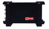
MSO license - LA2540C
The 16 integrated digital channels are displayed along-side analog channels allowing users to view up to 18 time-correlated channels with shared triggering and acquisition on one screen. The LA2540C license enables the 16 digital channels of the 2540C Series and is included with MSO models.
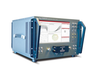
16 channel logic probe - LP2540C
The 16-channel color-coded logic probe consists of two eight-channel pods. To make contact with the DUT, the probe connects directly to square pins or clips to test points using the included grabbers. With an input capacitance of only 8 pF and 100 kω input impedance, the probe protects the integrity of your signal. The probe is included with MSO models.
Decode license - DC2540C
Select up to 2 serial bus protocols I²C, SPI, UART/RS232, CAN, and LIN and decode concurrently from analog and MSO channels. Decode information in real-time and display in binary, decimal, hex, or ASCII.
Buy now, upgrade later
Install the MSO and decode licenses at any time or try before you buy with the 30-day trial license on each model. Any DSO model in the 2540C Series can be upgraded to an MSO. Installation is quick and easily done within the oscilloscope menu.
The 2544C is a 200 MHz, 2 Channel digital oscilloscope from BK Precision. Digital oscilloscopes make use of binary numbers that correspond to samples of the electronic equipment’s voltage. This is in contrast to analog oscilloscopes, which use continually varying voltages. Digital oscilloscopes use an analog-to-digital converter (ADC) to convert the voltages it measures into digital information
Additional Features:
- 1 GSa/s sample rate
- 14 Mpts maximum record length
- 16 digital channels with logic analyzer (MSO upgrade)
- Serial bus decoding supporting I²C, SPI, UART/RS232, CAN, and LIN protocols (Decode upgrade)
- Built-in Function and Arbitrary Waveform Generator comes standard on all models
- Large 8” widescreen display with 256-level color gradient
- 60,000 wfms/s maximum waveform capture rate
- Compact footprint and lightweight
- High speed hardware-based pass/fail testing function and masking
- Segmented acquisition history waveform record function (record length up to 80,000 frames)
- Trigger types: Edge, Slope, Pulse, Video, Window, Runt, Interval, Dropout, Pattern, Serial
- FFT including seven other math functions: Addition, Subtraction, Multiplication, Division, Integration, Differential, and Square Root
- 36 automatic measurements supporting statistics, gating, math, history and reference measurements
- Multi-language user interface and built-in context sensitive help
- Software provided for remote PC control
- Front panel USB port for saving and recalling waveforms, setups, and screenshots
- Standard LAN and USBTMC-compliant USB device port
- Selectable 50Ω and 1 MΩ input coupling
- Included Accessories: Passive probes (one per channel), power cord, certificate of calibration, USB (Type A to B) communication cable
- Optional Accessories: 16-channel digital logic probe (LP2540C)
- Three-Year Warranty
Performance Characteristics
- Bandwidth: 200 MHz
- Rise Time: <5 ns / <3.5 ns / <1.8 ns
- Sample Rate: 1 GSa/s (single channel), 500 MSa/s (dual channel)
- Input Channels Analog: 2
- Digital: 16 (-MSO models or with LA2540C upgrade)
- Memory Depth: 14 Mpts (single channel), 7 Mpts (dual channel)
- Waveform Update Rate: 60,000 wfms/s
- Hardware Bandwidth Limits: 20 MHz
- Input Coupling: DC, AC, GND
- Input Impedance: 1 M Ω ± 2% || (22 pF ±3 pF); 50 Ω ± 2%
- Ch to Ch Isolation: >40dB
Acquisition System
- Peak Detect: 1 ns
- Average: 4, 16, 32, 64, 128, 256, 512, 1024
- Enhanced Resolution: 0.5, 1, 1.5, 2., 2.5, 3 bits selectable
- Interpolation: Sin(x)/x, Linear
Vertical System
- Vertical Resolution: 8 bits
- Vertical Sensitivity: 500 µV/div to 10 V/div (1-2-5)
- Maximum Input Voltage: 1 M Ω < 400 Vpk; 50 Ω <5 Vrms
- DC Gain Accuracy: ±3%: 5 mV/div to 10 V/div; ±4%: < 2 mV/div
Horizontal System
- Time Base Range: 2.0 ns/div to 50 s/div
- Time Base Accuracy: ±25 ppm
- Ch to Ch Deskew Range: ±100 ns
Trigger System
- Modes: Auto, Normal, Single
- Coupling: DC, AC, LF Reject, HF Reject, Noise Reject Ch1-Ch2
- Trigger Level: Internal: ±4.5 div from center; External: EXT: ±0.6 V; EXT/5: ±3 V
- Hold-Off Range: 100 ns to 1.5 s
- Types: Edge, Slope, Pulse, Video, Window, Interval, Dropout, Runt, Pattern
- Serial Trigger: I²C, SPI, UART/RS232, CAN, LIN
Cursors
- Mode: Manual, Track
- Measurements: ΔT, 1/ΔT, X2, X1, ΔV, Y2, Y1
Waveform Math
- Math Operation: Add, Subtract, Multiply, Divide, FFT, Derivative, Integral, Square Root
- FFT: Windows: Rectangle, Blackman, Hanning, Hamming, Flattop
Waveform Measurements
- Voltage: Vpp, Vmax, Vmin, Vamp, Vtop, Vbase, Mean, Cmean, Stdev, Cstd, Vrms, Crms, FOV, FPRE, ROV, RPRE, Level@Trigger
- Time: +SR, -SR, Period, Freq, +Width, -Width, Rise, Fall, BWidth, +Duty, -Duty, Time@Mid
- Delay: Phase, FRR, FRF, FFR, FFF, LRR, LRF, LFF, Skew
- Statistics: Current, Mean, Min, Max, Stdev, Count
- Gating: Time domain
I/O Interface
- Standard: USB Host, USB Device, LAN, Pass/Fail, Trigger Out
- Pass/Fail: 3.3 V TTL Output
Display System
- Display: 8” Color TFT-LCD, 800 x 480 Resolution
- Wave Display Mode: Vectors, Dots
- Persistence: Off, Infinite, 1 sec, 5 sec, 10 sec, 30 sec
- Intensity Grading: 256 Levels
- Language: Simplified Chinese, Traditional Chinese, English, French, Japanese, Korean, German, Russian, Italian, Portuguese
Environmental and Safety
- Temperature: Operating: 10 °C to +40 °C; Storage: -20 °C to +60 °C
- Humidity: Operating: 85% RH, 40 °C, 24 hours; Storage: 85% RH, 65 °C, 24 hours
- Altitude: Operating: 3,000 m; Storage: 15,266 m
- Electromagnetic Compatibility: EMC Directive 2004/108/EC, EN61326:2006
- Safety: Low Voltage Directive 2006/95/EC, EN61010-1:2001
General
- Power Requirements: 100 to 240 VAC, CAT II, 50 VA Max, 45 Hz to 440 Hz
- Dimensions (W x H x D): 4.8” x 7.2” x 13.4” (123 x 184 x 340 mm)
- Weight: 7.3 lbs (3.3 kg)
Function/Arbitrary Waveform Generator
- Waveforms: Sine, Square, Ramp, Pulse, DC, Noise, Cardiac, Gaus Pulse, Exp Rise
- Arbitrary: 4 Slots for Arbitrary Waveforms
- Maximum Output Frequency: 25 MHz
- Sample Rate: 125 MSa/s
- Frequency Resolution: 1 µHz
- Frequency Accuracy ±50 ppm
- Vertical Resolution: 14 bits
- Amplitude Range: -1.5 to +1.5 V @ 50 Ω; -3 to +3 V @ 1 MΩ
- Output Impedance: 50 Ω ±2%
- Protection: Short-Circuit Protection
Sine Characteristics
- Frequency: 1 µHz to 25 MHz
- Offset Accuracy (100 kHz): ±(0.3 dB * Offset Setting Value + 1 mVpp)
- Amplitude flatness: ±0.3 dB (100 kHz, 5 Vpp)
- Spurious (non harmonics): DC to 1 MHz: -60 dBc; 1 MHz to 5 MHz: -55 dBc; 5 MHz to 25 MHz: -50 dBc
- Harmonic distortion: DC to 5 MHz: -50 dBc; 5 MHz to 25 MHz: -45 dBc
Square/Pulse Characteristics
- Frequency: 1 µHz to 10 MHz
- Duty Cycle: 20% to 80%
- Rise/Fall Time: < 24 ns (10% to 90%)
- Overshoot (1 kHz, 1 Vpp Typical): < 3%
- Pulse Width: > 50 ns
- Jitter: < 500 ps + 10 ppm
Ramp Characteristics
- Frequency: 1 µHz to 300 kHz
- Linearity (Typical): < 0.1% of Pk-Pk (Typical, 1 kHz, 1 Vpp, 100% Symmetry)
- Symmetry: 0% to 100% (Adjustable)
DC Characteristics
- Offset Range: ±1.5 V (50 O) ±3 V (High-Z)
- Accuracy: ± (|offset|*1%+3 mV)
Noise Characteristics
- Bandwidth: > 25 MHz (-3 dB)
- Arbitrary Wave Characteristics
- Frequency: 1 µHz to 5 MHz
- Wave Length: 16 Kpts
- Sample Rate: 125 MSa/s
Serial Decoder (DC2540C)
- Threshold: -4.5 to 4.5 div
- Recorded List: 1 to 7 Lines
I²C Decoder
- Signal: SCL, SDA
- Address: 7 bit, 10 bit
SPI Decoder
- Signal: CLK, MISO, MOSI, CS
- Edge Select: Rising Falling
- Idle Level: Low, High
- Bit Order: MSB, LSB
UART/RS232 Decoder
- Signal: RX, TX
- Data Width: 5, 6, 7, 8 bit
- Parity Check: None, Odd, Even
- Stop Bit: 1, 1.5, 2 bit
- Idle Level: Low, High
CAN Decoder
- Signal: CAN_H, CAN_L
- Source: CAN_H, CAN_L, CAN_H-CAN_L
LIN Decoder
- Supported Specification: Ver1.3, Ver2.0
The 2544C Digital Storage Oscilloscope delivers advanced features and debug capabilities for a wide range of applications at an entry-level price point. With up to 200 MHz bandwidth in a 2-channel configuration, each model offers a sample rate of 1 GSa/s, and a maximum memory depth of 14 Mpts. In addition, these oscilloscopes provide an 8” color display with 256 levels of color grading combined with a high waveform update rate up to 60,000 wfrms/sec, which allows the instruments to capture infrequent glitches with excellent signal fidelity. The logic analyzer and decode software provides 16 additional digital channels and serial bus decoding for I²C, SPI, UART/RS232, CAN, and LIN protocols.
Maximize productivity using extensive features such as digital filtering, waveform recording, pass/fail limit testing, and automatic measurements. The built-in 25 MHz function/arbitrary waveform generator (AWG) comes standard with all models and provides stimulus output of 4 arbitrary waveforms, sine, square, ramp, pulse, DC, noise, cardiac, Gaussian pulse, and exponential rise/fall waveforms to the device under test.
The 2540C Series oscilloscopes are ideal for applications in design, education, service, and repair. This instrument offers a comprehensive set of tools to capture signal anomalies, decode serial bus protocols, and help speed up debug and analysis. The MSO and decoding functionalities are available for upgrade in the field with the purchase of a license key.
All traditional digital oscilloscope features come standard in the 2540C Series: Cursors, 50 Ω input coupling, reference signals, persist, rolling, noise rejection and deskew.
Waveform History and Recording
Quickly scroll through millions of points with History Mode’s playback functionality to find difficult to capture events. Eliminate unnecessary idle signals and dead-time by selectivity capturing up to 80,000 segments.
Function and Arbitrary Waveform Generator
A powerful 25 MHz function/arbitrary waveform generator comes standard in the 2540C Series. Use complimentary software to generate waveforms and load up to 4 arbitrary waveforms into the instrument. Built-in functions are sine, square, ramp, pulse, DC, noise, cardiac, Gaussian pulse, and exponential rise/fall.
Automatic Waveform Math and Measurement
Display 36 automated measurements that include voltage, time, and statistics. Arithmetic and FFT functions can be performed on analog channels and two reference signals.
Color Grading
With 256 levels of color grading, the most common occurrences are represented in red and the least common are represented in purple. Easily spot outliers as they will persist for a user specified time.
Hardware Pass/Fail and Masking
Perform up to 60,000 pass/fail decisions a second. Easy to generate masking templates help capture anomalies even with complicated waveforms.
PC connectivity
PC software is provided (free download at www.bkprecision.com) for seamless integration between the oscilloscope and PC. Capture and transfer waveforms, screen images, setups and measurement results to a Windows PC via the USB device port on the back of the instrument. A USB host port on the front allows for quick and easy screen saving.
MSO license - LA2540C
The 16 integrated digital channels are displayed along-side analog channels allowing users to view up to 18 time-correlated channels with shared triggering and acquisition on one screen. The LA2540C license enables the 16 digital channels of the 2540C Series and is included with MSO models.
16 channel logic probe - LP2540C
The 16-channel color-coded logic probe consists of two eight-channel pods. To make contact with the DUT, the probe connects directly to square pins or clips to test points using the included grabbers. With an input capacitance of only 8 pF and 100 kΩ input impedance, the probe protects the integrity of your signal. The probe is included with MSO models.
Decode license - DC2540C
Select up to 2 serial bus protocols I²C, SPI, UART/RS232, CAN, and LIN and decode concurrently from analog and MSO channels. Decode information in real-time and display in binary, decimal, hex, or ASCII.
Buy now, upgrade later
Install the MSO and decode licenses at any time or try before you buy with the 30-day trial license on each model. Any DSO model in the 2540C Series can be upgraded to an MSO. Installation is quick and easily done within the oscilloscope menu.