American High Voltage, Inc. HR Series HR-1P

Description
Half Rack Laboratory Use Output Voltage: HR series are available in multiple output voltages ranging from +/-1,000VDC to +/-125,000VDC Power: 100W Dimension: 20.00” x 9.00” x 3.50” Electrical Characteristics & Description The HR series power supplies are a proven high quality low cost resonant switching design. They produce up to 100 watts of high voltage power. They are only 1/2 the width of a normal 19-inch rack, therefore are ideal for bench work. This series has been designed for laboratory use utilizing bright red LED voltage and current digital meters. Both voltage and current are adjustable from front panel 10-turn potentiometers. The units can also be remotely programmed by voltage or resistance. Remote controls are via a 9 pin D connector located on the back of the unit. An external enable is offered for safety. The standard input voltage is 115 VAC, 50 - 100 Hz. Other voltages are available upon request. All units offer SLO-start feature with ramp up time less than 3 seconds. The high voltage output is through a coax cable assembly located in the rear of the chassis. This chassis is not grounded and allows the output to be floated above the case by 50 VDC.All units feature arc protection and stability greater than 200 ppm/C. The HR Series high voltage power supplies are regulated by virtue of a resonant -sine wave Pulse Width Modulation topology. Here, a pulse driver converts a duty-cycle modulated square wave into a sinusoidal waveform by means of a high-Q resonant tank circuit. By using a resonant circuit, the high efficiency pulse dive is now converted to an amplitude modulated waveform which is stepped up by a high frequency high voltage transformer. The output from the transformer is fed into a high voltage multiplier circuit which converts the AC into a high voltage DC output. The DC output is regulated by a high gain closed loop circuit which adjusts for both line and load variations to within 0.01%. Since the HR series is both voltage and current regulated, two independent control loops operate in an automatic cross-over method. The front panel knobs for voltage and current set the limiting values. The HR series may be both voltage and resistance programmed. An internal reference voltage of 11.5 VDC is adjusted down as shown in Figure 1 below and used as signal input to the non-inverting pin of an operational amplifier. The closed feedback loop senses the output voltage and feeds this signal back to the inverting pin of the operational amplifier. Both voltage and current are regulated in this manner. By adjusting the control with either a resistance to ground or an external voltage source, the feedback loop is adjusted ?
Description
Half Rack Laboratory Use Output Voltage: HR series are available in multiple output voltages ranging from +/-1,000VDC to +/-125,000VDC Power: 100W Dimension: 20.00” x 9.00” x 3.50” Electrical Characteristics & Description The HR series power supplies are a proven high quality low cost resonant switching design. They produce up to 100 watts of high voltage power. They are only 1/2 the width of a normal 19-inch rack, therefore are ideal for bench work. This series has been designed for laboratory use utilizing bright red LED voltage and current digital meters. Both voltage and current are adjustable from front panel 10-turn potentiometers. The units can also be remotely programmed by voltage or resistance. Remote controls are via a 9 pin D connector located on the back of the unit. An external enable is offered for safety. The standard input voltage is 115 VAC, 50 - 100 Hz. Other voltages are available upon request. All units offer SLO-start feature with ramp up time less than 3 seconds. The high voltage output is through a coax cable assembly located in the rear of the chassis. This chassis is not grounded and allows the output to be floated above the case by 50 VDC.All units feature arc protection and stability greater than 200 ppm/C. The HR Series high voltage power supplies are regulated by virtue of a resonant -sine wave Pulse Width Modulation topology. Here, a pulse driver converts a duty-cycle modulated square wave into a sinusoidal waveform by means of a high-Q resonant tank circuit. By using a resonant circuit, the high efficiency pulse dive is now converted to an amplitude modulated waveform which is stepped up by a high frequency high voltage transformer. The output from the transformer is fed into a high voltage multiplier circuit which converts the AC into a high voltage DC output. The DC output is regulated by a high gain closed loop circuit which adjusts for both line and load variations to within 0.01%. Since the HR series is both voltage and current regulated, two independent control loops operate in an automatic cross-over method. The front panel knobs for voltage and current set the limiting values. The HR series may be both voltage and resistance programmed. An internal reference voltage of 11.5 VDC is adjusted down as shown in Figure 1 below and used as signal input to the non-inverting pin of an operational amplifier. The closed feedback loop senses the output voltage and feeds this signal back to the inverting pin of the operational amplifier. Both voltage and current are regulated in this manner. By adjusting the control with either a resistance to ground or an external voltage source, the feedback loop is adjusted ?

Suppliers

Company
Product
Description
Supplier Links
HR Series HR-1P
Half Rack Laboratory Use Output Voltage: HR series are available in multiple output voltages ranging from +/-1,000VDC to +/-125,000VDC Power: 100W Dimension: 20.00” x 9.00” x 3.50” Electrical Characteristics & Description The HR series power supplies are a proven high quality low cost resonant switching design. They produce up to 100 watts of high voltage power. They are only 1/2 the width of a normal 19-inch rack, therefore are ideal for bench work. This series has been designed for laboratory use utilizing bright red LED voltage and current digital meters. Both voltage and current are adjustable from front panel 10-turn potentiometers. The units can also be remotely programmed by voltage or resistance. Remote controls are via a 9 pin D connector located on the back of the unit. An external enable is offered for safety. The standard input voltage is 115 VAC, 50 - 100 Hz. Other voltages are available upon request. All units offer SLO-start feature with ramp up time less than 3 seconds. The high voltage output is through a coax cable assembly located in the rear of the chassis. This chassis is not grounded and allows the output to be floated above the case by 50 VDC.All units feature arc protection and stability greater than 200 ppm/C. The HR Series high voltage power supplies are regulated by virtue of a resonant -sine wave Pulse Width Modulation topology. Here, a pulse driver converts a duty-cycle modulated square wave into a sinusoidal waveform by means of a high-Q resonant tank circuit. By using a resonant circuit, the high efficiency pulse dive is now converted to an amplitude modulated waveform which is stepped up by a high frequency high voltage transformer. The output from the transformer is fed into a high voltage multiplier circuit which converts the AC into a high voltage DC output. The DC output is regulated by a high gain closed loop circuit which adjusts for both line and load variations to within 0.01%. Since the HR series is both voltage and current regulated, two independent control loops operate in an automatic cross-over method. The front panel knobs for voltage and current set the limiting values. The HR series may be both voltage and resistance programmed. An internal reference voltage of 11.5 VDC is adjusted down as shown in Figure 1 below and used as signal input to the non-inverting pin of an operational amplifier. The closed feedback loop senses the output voltage and feeds this signal back to the inverting pin of the operational amplifier. Both voltage and current are regulated in this manner. By adjusting the control with either a resistance to ground or an external voltage source, the feedback loop is adjusted ?

Half Rack Laboratory Use
Output Voltage: HR series are available in multiple output voltages ranging from +/-1,000VDC to +/-125,000VDC
Power: 100W
Dimension: 20.00” x 9.00” x 3.50”

Electrical Characteristics & Description
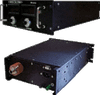
The HR series power supplies are a proven high quality low cost resonant switching design. They produce up to 100 watts of high voltage power. They are only 1/2 the width of a normal 19-inch rack, therefore are ideal for bench work. This series has been designed for laboratory use utilizing bright red LED voltage and current digital meters. Both voltage and current are adjustable from front panel 10-turn potentiometers. The units can also be remotely programmed by voltage or resistance. Remote controls are via a 9 pin D connector located on the back of the unit. An external enable is offered for safety.

The standard input voltage is 115 VAC, 50 - 100 Hz. Other voltages are available upon request. All units offer SLO-start feature with ramp up time less than 3 seconds.

The high voltage output is through a coax cable assembly located in the rear of the chassis. This chassis is not grounded and allows the output to be floated above the case by 50 VDC.All units feature arc protection and stability greater than 200 ppm/C.

The HR Series high voltage power supplies are regulated by virtue of a resonant -sine wave Pulse Width Modulation topology. Here, a pulse driver converts a duty-cycle modulated square wave into a sinusoidal waveform by means of a high-Q resonant tank circuit. By using a resonant circuit, the high efficiency pulse dive is now converted to an amplitude modulated waveform which is stepped up by a high frequency high voltage transformer. The output from the transformer is fed into a high voltage multiplier circuit which converts the AC into a high voltage DC output. The DC output is regulated by a high gain closed loop circuit which adjusts for both line and load variations to within 0.01%.

Since the HR series is both voltage and current regulated, two independent control loops operate in an automatic cross-over method. The front panel knobs for voltage and current set the limiting values.

The HR series may be both voltage and resistance programmed. An internal reference voltage of 11.5 VDC is adjusted down as shown in Figure 1 below and used as signal input to the non-inverting pin of an operational amplifier. The closed feedback loop senses the output voltage and feeds this signal back to the inverting pin of the operational amplifier. Both voltage and current are regulated in this manner.

By adjusting the control with either a resistance to ground or an external voltage source, the feedback loop is adjusted ?

Supplier's Site

Technical Specifications

  American High Voltage, Inc.
Product Category DC Power Supplies
Product Number HR-1P
Product Name HR Series
DC Output Voltage 0.0 to 1000.0 volts
Unlock Full Specs
to access all available technical data

Similar Products

Switched-mode power supply 24 V DC - DN4034 - ifm efector inc.
Specs
Technology Switching Power Supply
Form Factor DIN Rail
Operating Temperature -25 to 70 C (-13 to 158 F)
View Details
4 suppliers
Programmable Power Supply, ALTP 110/220VAC - S3425D - Fargo Controls, Inc.
Specs
Type Programmable Power Supply
Form Factor DIN Rail
Operating Temperature -20 to 60 C (-4 to 140 F)
View Details
VIPA SLIO Module, Power - 007-0AA00 - Yaskawa America, Inc. - Motion Division
Yaskawa America, Inc. - Motion Division
Specs
Type DC-DC Converter
Applications Instrumentation
Operating Temperature 0 to 60 C (32 to 140 F)
View Details
2 suppliers
PS250, PS600 and PS1000 Selectone® Standby Battery/Back-up Power Supplies - PS1000 - Federal Signal Corporation - Industrial Signaling and Systems
Federal Signal Corporation - Industrial Signaling and Systems
Specs
Form Factor Wall Mount
Regulatory Compliance UL
Operating Temperature 0 to 49 C (32 to 120 F)
View Details