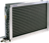
Fincoil L air conditioning coils are heating coils for ventilation and airconditioning plants. The internal heat transfer medium used in coil type L is water. In coil type LG, the medium is glycol or other solutions suitable for copper tubing. Special coils are also available for OEM-applications.
Standard configuration
F5 Coil - Tube pitch 35x30.31 mm staggered - Cu tubes 13.3 mm OD, aluminium fins - Fin spacing 2, 2.3, 2.5, 3, 4, 5, 6 and 7 mm (12 mm fin spacing available for limited no. of coil sizes) - Frame material: aluminium or galvanized steel - Special coils F5-E (copper or epoxy coated fins, stainless steel frame, custom frame dimensions)
F2 Coil - Tube pitch 28.87x25 mm staggered - Cu tubes 10 mm OD, aluminium fins - Fin spacing 2, 2.5, 3, 4 and 5 mm - Frame material: aluminium - Special coils F2-E (frame material galvanized or stainless steel, custom frame dimensions)
For all F coil types the tubes are attached to the fins by mechanical expansion and fin collars extend over the entire tubing surface (excl. 12 mm fin spacing). The staggered tube arrangement in combination with corrugated fins give the coil an excellent heat transfer efficiency. G ¼” plugs are provided for draining and venting on types L, LG, J and JG. If required, an G ¼” socket is also provided for an anti-freezing thermostat. A separate drip tray with a pipe connection is provided for each coil of type J, JG or Jx for the removal of the water condensing on the coil surfaces. The tube connections on the coils (as seen in air flow direction) are either on the right- or left-hand side. Unless otherwise specified, the coil is arranged in accordance with the counter-flow principle.
Options
For a full overview of all available options and additional technical specifications please refer to the product leaflet.
Fincoil L air conditioning coils are heating coils for ventilation and airconditioning plants. The internal heat transfer medium used in coil type L is water. In coil type LG, the medium is glycol or other solutions suitable for copper tubing. Special coils are also available for OEM-applications.
Standard configuration
- F5 Coil
- Tube pitch 35x30.31 mm staggered
- Cu tubes 13.3 mm OD, aluminium fins
- Fin spacing 2, 2.3, 2.5, 3, 4, 5, 6 and 7 mm (12 mm fin spacing available for limited no. of coil sizes)
- Frame material: aluminium or galvanized steel
- Special coils F5-E (copper or epoxy coated fins, stainless steel frame, custom frame dimensions)
- F2 Coil
- Tube pitch 28.87x25 mm staggered
- Cu tubes 10 mm OD, aluminium fins
- Fin spacing 2, 2.5, 3, 4 and 5 mm
- Frame material: aluminium
- Special coils F2-E (frame material galvanized or stainless steel, custom frame dimensions)
- For all F coil types the tubes are attached to the fins by mechanical expansion and fin collars extend over the entire tubing surface (excl. 12 mm fin spacing). The staggered tube arrangement in combination with corrugated fins give the coil an excellent heat transfer efficiency.
G ¼” plugs are provided for draining and venting on types L, LG, J and JG. If required, an G ¼” socket is also provided for an anti-freezing thermostat.
A separate drip tray with a pipe connection is provided for each coil of type J, JG or Jx for the removal of the water condensing on the coil surfaces. The tube connections on the coils (as seen in air flow direction) are either on the right- or left-hand side. Unless otherwise specified, the coil is arranged in accordance with the counter-flow principle.
Options
For a full overview of all available options and additional technical specifications please refer to the product leaflet.