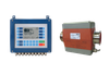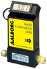

The GFM17S-VADL2-A0 is a low-cost mass flowmeter designed for measuring gas flow rates with a maximum pressure of 1000 psig (70 bars) and a leak integrity of 1 x 10^{-9} smL/sec of helium. It features a rigid metallic construction and is available with NIST traceable certification. The device includes a built-in tiltable LCD readout and provides output signals of 0-5 Vdc and 4-20 mA, making it suitable for various applications. The flowmeter operates based on a laminar flow principle, ensuring consistent flow rate measurements that are unaffected by temperature and pressure variations within specified limits. It is compact and can be used as a portable device, with options for totalizer functionality. The GFM17S model is constructed from stainless steel and is compatible with 1/4" compression fittings. Its accuracy is ¬±1.0% of full scale, with a repeatability of ¬±0.25% of full scale and a response time of approximately 2 seconds. The operating temperature range for gas is between 32 ¬8F to 122 ¬8F (0 ¬8C to 50 ¬8C), and for ambient conditions, it is from 14 ¬8F to 122 ¬8F (-10 ¬8C to 50 ¬8C).
Metered gases are divided into two laminar
flow paths, one through the primary flow
conduit, and the other through a capillary
sensor tube. Both flow conduits are
designed to ensure laminar flows and there-
fore the ratio of their flow rates is constant.
Two precision temperature sensing
windings on the sensor tube are heated,
and when flow takes place, gas carries heat
from the upstream to the downstream wind-
ings. The resultant temperature
differential is proportional to the change in
resistance of the sensor windings.
A Wheatstone bridge design is used to
monitor the temperature dependent resist-
ance gradient on the sensor windings
which is linearly proportional to the
instantaneous rate of flow.
Metered gases are divided into two laminar
flow paths, one through the primary flow
conduit, and the other through a capillary
sensor tube. Both flow conduits are
designed to ensure laminar flows and there-
fore the ratio of their flow rates is constant.
Two precision temperature sensing
windings on the sensor tube are heated,
and when flow takes place, gas carries heat
from the upstream to the downstream wind-
ings. The resultant temperature
differential is proportional to the change in
resistance of the sensor windings.
A Wheatstone bridge design is used to
monitor the temperature dependent resist-
ance gradient on the sensor windings
which is linearly proportional to the
instantaneous rate of flow.
Metered gases are divided into two laminar
flow paths, one through the primary flow
conduit, and the other through a capillary
sensor tube. Both flow conduits are
designed to ensure laminar flows and there-
fore the ratio of their flow rates is constant.
Two precision temperature sensing
windings on the sensor tube are heated,
and when flow takes place, gas carries heat
from the upstream to the downstream wind-
ings. The resultant temperature
differential is proportional to the change in
resistance of the sensor windings.
A Wheatstone bridge design is used to
monitor the temperature dependent resist-
ance gradient on the sensor windings
which is linearly proportional to the
instantaneous rate of flow.
Metered gases are divided into two laminar
flow paths, one through the primary flow
conduit, and the other through a capillary
sensor tube. Both flow conduits are
designed to ensure laminar flows and there-
fore the ratio of their flow rates is constant.
Two precision temperature sensing
windings on the sensor tube are heated,
and when flow takes place, gas carries heat
from the upstream to the downstream wind-
ings. The resultant temperature
differential is proportional to the change in
resistance of the sensor windings.
A Wheatstone bridge design is used to
monitor the temperature dependent resist-
ance gradient on the sensor windings
which is linearly proportional to the
instantaneous rate of flow.
Metered gases are divided into two laminar
flow paths, one through the primary flow
conduit, and the other through a capillary
sensor tube. Both flow conduits are
designed to ensure laminar flows and there-
fore the ratio of their flow rates is constant.
Two precision temperature sensing
windings on the sensor tube are heated,
and when flow takes place, gas carries heat
from the upstream to the downstream wind-
ings. The resultant temperature
differential is proportional to the change in
resistance of the sensor windings.
A Wheatstone bridge design is used to
monitor the temperature dependent resist-
ance gradient on the sensor windings
which is linearly proportional to the
instantaneous rate of flow.
Metered gases are divided into two laminar
flow paths, one through the primary flow
conduit, and the other through a capillary
sensor tube. Both flow conduits are
designed to ensure laminar flows and there-
fore the ratio of their flow rates is constant.
Two precision temperature sensing
windings on the sensor tube are heated,
and when flow takes place, gas carries heat
from the upstream to the downstream wind-
ings. The resultant temperature
differential is proportional to the change in
resistance of the sensor windings.
A Wheatstone bridge design is used to
monitor the temperature dependent resist-
ance gradient on the sensor windings
which is linearly proportional to the
instantaneous rate of flow.
Metered gases are divided into two laminar
flow paths, one through the primary flow
conduit, and the other through a capillary
sensor tube. Both flow conduits are
designed to ensure laminar flows and there-
fore the ratio of their flow rates is constant.
Two precision temperature sensing
windings on the sensor tube are heated,
and when flow takes place, gas carries heat
from the upstream to the downstream wind-
ings. The resultant temperature
differential is proportional to the change in
resistance of the sensor windings.
A Wheatstone bridge design is used to
monitor the temperature dependent resist-
ance gradient on the sensor windings
which is linearly proportional to the
instantaneous rate of flow.
Metered gases are divided into two laminar
flow paths, one through the primary flow
conduit, and the other through a capillary
sensor tube. Both flow conduits are
designed to ensure laminar flows and there-
fore the ratio of their flow rates is constant.
Two precision temperature sensing
windings on the sensor tube are heated,
and when flow takes place, gas carries heat
from the upstream to the downstream wind-
ings. The resultant temperature
differential is proportional to the change in
resistance of the sensor windings.
A Wheatstone bridge design is used to
monitor the temperature dependent resist-
ance gradient on the sensor windings
which is linearly proportional to the
instantaneous rate of flow.
Metered gases are divided into two laminar
flow paths, one through the primary flow
conduit, and the other through a capillary
sensor tube. Both flow conduits are
designed to ensure laminar flows and there-
fore the ratio of their flow rates is constant.
Two precision temperature sensing
windings on the sensor tube are heated,
and when flow takes place, gas carries heat
from the upstream to the downstream wind-
ings. The resultant temperature
differential is proportional to the change in
resistance of the sensor windings.
A Wheatstone bridge design is used to
monitor the temperature dependent resist-
ance gradient on the sensor windings
which is linearly proportional to the
instantaneous rate of flow.
Metered gases are divided into two laminar
flow paths, one through the primary flow
conduit, and the other through a capillary
sensor tube. Both flow conduits are
designed to ensure laminar flows and there-
fore the ratio of their flow rates is constant.
Two precision temperature sensing
windings on the sensor tube are heated,
and when flow takes place, gas carries heat
from the upstream to the downstream wind-
ings. The resultant temperature
differential is proportional to the change in
resistance of the sensor windings.
A Wheatstone bridge design is used to
monitor the temperature dependent resist-
ance gradient on the sensor windings
which is linearly proportional to the
instantaneous rate of flow.
| Aalborg Instruments | Aalborg Instruments | Aalborg Instruments | Aalborg Instruments | Aalborg Instruments | Aalborg Instruments | Aalborg Instruments | Aalborg Instruments | Aalborg Instruments | Aalborg Instruments | |
|---|---|---|---|---|---|---|---|---|---|---|
| Product Category | Flow Meters | Flow Meters | Flow Meters | Flow Meters | Flow Meters | Flow Meters | Flow Meters | Flow Meters | Flow Meters | Flow Meters |
| Product Number | GFM17S-VADL2-A0 | GFM17S-VADL2-A0 | GFM17S-VADL2-A0 | GFM17S-VADL2-A0 | GFM17S-VADL2-A0 | GFM17S-VADL2-A0 | GFM17S-VADL2-A0 | GFM17S-VADL2-A0 | GFM17S-VADL2-A0 | GFM17S-VADL2-A0 |
| Product Name | Low Cost Mass Flowmeter | Low Cost Mass Flowmeter | Low Cost Mass Flowmeter | Low Cost Mass Flowmeter | Low Cost Mass Flowmeter | Low Cost Mass Flowmeter | Low Cost Mass Flowmeter | Low Cost Mass Flowmeter | Low Cost Mass Flowmeter | Low Cost Mass Flowmeter |
| Meter Technology | Thermal | Thermal | Thermal | Thermal | Thermal | Thermal | Thermal | Thermal | Thermal | Thermal |
| Meter Type | Mass Flow Meter; Volumetric Flow Meter | Mass Flow Meter; Volumetric Flow Meter | Mass Flow Meter; Volumetric Flow Meter | Mass Flow Meter; Volumetric Flow Meter | Mass Flow Meter; Volumetric Flow Meter | Mass Flow Meter; Volumetric Flow Meter | Mass Flow Meter; Volumetric Flow Meter | Mass Flow Meter; Volumetric Flow Meter | Mass Flow Meter; Volumetric Flow Meter | Mass Flow Meter; Volumetric Flow Meter |
| Features | Recorder / Totalizer Functions (optional feature) | Recorder / Totalizer Functions (optional feature) | Recorder / Totalizer Functions (optional feature) | Recorder / Totalizer Functions (optional feature) | Recorder / Totalizer Functions (optional feature) | Recorder / Totalizer Functions (optional feature) | Recorder / Totalizer Functions (optional feature) | Recorder / Totalizer Functions (optional feature) | Recorder / Totalizer Functions (optional feature) | Recorder / Totalizer Functions (optional feature) |
| Approvals | CE, ISO 9001, UKAS Quality | CE, ISO 9001, UKAS Quality | CE, ISO 9001, UKAS Quality | CE, ISO 9001, UKAS Quality | CE, ISO 9001, UKAS Quality | CE, ISO 9001, UKAS Quality | CE, ISO 9001, UKAS Quality | CE, ISO 9001, UKAS Quality | CE, ISO 9001, UKAS Quality | CE, ISO 9001, UKAS Quality |
| Operating Temperature | 41 to 122 F (5 to 50 C) | 41 to 122 F (5 to 50 C) | 41 to 122 F (5 to 50 C) | 41 to 122 F (5 to 50 C) | 41 to 122 F (5 to 50 C) | 41 to 122 F (5 to 50 C) | 41 to 122 F (5 to 50 C) | 41 to 122 F (5 to 50 C) | 41 to 122 F (5 to 50 C) | 41 to 122 F (5 to 50 C) |