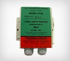
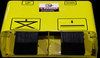
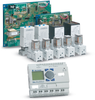
The Model 915 Cable Length Monitor is designed to prevent the accidental pulling out or breaking of the shuttle car cable or roof bolter. The Cable Monitor utilizes a sensor located near the cable reel to shut down the machine when 10 to 15 feet of cable remain on the reel. The Model 915 consist of three main parts. (1)The control unit, which is mounted in the operators compartment, has test and reset switch with red and green LED. When the machine stops the operator can press and hold the reset switch and back up the machine. The power supply unit must be mounted in the control compartment. (3)The sensor mounts in the cable reel area. Complete mounting and operation instructions are provided.
When installed properly on the equipment, the cable length monitor will interrupt the control line voltage thus stopping the machine. The switch assembly must be installed so that the magnets that are attached to the trailing cable pass over the switches. When the magnets pass over the switches the red LED on the operators control Unit will blink. The red LED will continue to flash until the machine is backed up to clear the magnets from the switch area. To back the machine up , hold the reset button in. To test the unit, push the TEST button. Periodic testing is recommended.
Durable
Potted PVC tubing - sensor
120 VAC
Optional 12 VDC/switches
300 Volt DC
Reset Switch.
Test Switch.
MSHA Id, # 503 Model 915
110 Volt AC Model 915 DC
12 Volt DC / switches 300 Volt DC
Stainless Steel Enclosure.
The Model 915 Cable Length Monitor is designed to prevent the accidental pulling out or breaking of the shuttle car cable or roof bolter. The Cable Monitor utilizes a sensor located near the cable reel to shut down the machine when 10 to 15 feet of cable remain on the reel. The Model 915 consist of three main parts. (1)The control unit, which is mounted in the operators compartment, has test and reset switch with red and green LED. When the machine stops the operator can press and hold the reset switch and back up the machine. The power supply unit must be mounted in the control compartment. (3)The sensor mounts in the cable reel area. Complete mounting and operation instructions are provided.
When installed properly on the equipment, the cable length monitor will interrupt the control line voltage thus stopping the machine. The switch assembly must be installed so that the magnets that are attached to the trailing cable pass over the switches. When the magnets pass over the switches the red LED on the operators control Unit will blink. The red LED will continue to flash until the machine is backed up to clear the magnets from the switch area. To back the machine up , hold the reset button in. To test the unit, push the TEST button. Periodic testing is recommended.
- Durable
- Potted PVC tubing - sensor
- 120 VAC
- Optional 12 VDC/switches
- 300 Volt DC
- Reset Switch.
- Test Switch.
- MSHA Id, # 503
Model 915
Model 915 DC
- 12 Volt DC / switches 300 Volt DC
- Stainless Steel Enclosure.