
Description
Rigid-Flex Circuits Benefits
Rigid-Flex PCB are used extensively in applications and industries including:
Rigid-Flex PCB Capability:
Items Mass Production Low Volume
Total Layers 2~16L 20L
Layers of sofe 10L 16L
PCB Thickness ≤2.4mm /
Line width/Line space Inner layer 3mil/3mil (HOz) 2.5mil/2.5mil (HOz)
Outer layer 4mil/4mil (1Oz) 3mil/3mil (1Oz)
Hole Ring ≥6mil 4mil
Impedance Control +/-10% /
Drilling Machine drilling ≥8mil 6mil
Laser drilling 5mil/6mil 4mil
Aspect Ratio 10:01 16:01
Surface Coating ENIG, Immersion Silver, Immersion Tin, OSP
Rigid-flex Attributes:
Material Fr4+PI
Layers 6L buried holes 2-4Layer
Copper thickness 1oz
Board thickness 1mm
Surface treatment HAL Leadfree
Track width/Space 5/5mil
Hole size 0.3mm
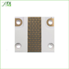
What is a Rigid-Flex PCB?
As the name suggests, a flexible printed circuit is a pattern of conductors printed onto a flexible insulating film. Rigid-flex is the name given to a printed circuit that is a combination of both flexible circuit(s) and rigid circuit(s), as shown in the image above. This combination is ideal for exploiting the benefits of both flexible and rigid circuits – the rigid circuits can carry all or the bulk of the components, with the flexible sections acting as interconnections between the rigid sections.
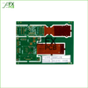
Rigid flex printed circuit boards are boards using a combination of flexible and rigid board technologies in an application.
Most rigid flex boards consist of multiple layers of flexible circuit substrates attached to one or more rigid boards externally and/or internally, depending upon the design of the application.
Designing a flex or rigid-flex circuit is very much an electromechanical process. Designing any PCB is a 3 dimensional design process, but for a flex or rigid-flex design the 3 dimensional requirements are much more important. Why, because the rigid-flex board may attach to multiple surfaces within the product enclosure, and this attachment will probably happen as part of the product assembly process. To ensure that all sections of the finished board fit in their folded location within the enclosure, it is strongly recommended that a mechanical mock up (also known as a paper doll cut out) is created. This process must be as accurate and realistic as possible with all possible mechanical and hardware elements included, and both the assembly-time phase and the finished assembly must be carefully analyzed.
Benefits of Rigid-Flex PCBs
• Space requirements can be minimized by applying 3D
• By removing the need for connectors and cables between the individual rigid parts, the board size and overall system weight can be reduced.
• By maximizing space, there is often a lower count in parts.
• Fewer solder joints assure higher connection reliability.
• Handling during assembly is easier in comparison with flexible boards.
• Simplified PCB assembly processes.
• Integrated ZIF contacts provide simple modular interfaces to the system environment.
• Test conditions are simplified. A complete test before installation becomes possible.
• Logistical and assembly costs are significantly reduced with Rigid-Flex boards.
• It is possible to increase the complexity of mechanical designs, which also improves the degree of freedom for optimized housing solutions.
| FX PCB Co., Ltd. | |
|---|---|
| Product Category | Printed Circuit Substrate Materials (PCB / PWB) |
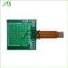
| Product Name | Rigid-Flex PCB 6 Layer |
| Type | Film / Flexible; Rigid |