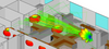


When the signal traverses a network, the jitter generated by the DUT becomes the input jitter to the next part of the network. If this jitter is amplified, it can exceed the jitter tolerance of the subsequent DUT. In this way, excessive jitter may accumulate and cause errors as the signal progresses through the network equipment.
Now, Jitter Generation and Measurement, Pulse Mask Compliance (XX012) application is available as a part of basic applications in T1 E1 analyzer.
GL's Jitter Generation software has been developed to generate jittered output T1/E1 signal with user-selected frequency and amplitude. It is suitable for testing jitter tolerance and compliance with standards such as G.823. In conjunction with GL's Jitter Measurement application, Jitter Generation may be also be used to test and measure jitter transfer.
The jitter generation capability is available in GL's Dual T1/E1 Express (PCIe) Boards, Universal T1 E1 Boards, and tProbe™ T1/E1 Analyzer units.
GL’s Pulse Shape Measurement software is also available as a part of Jitter Generation and Measurement application. It can determine if the pulse shape fits within a “pulse mask” as specified by standards ITU G.703 and ANSI T1.102-1993.
Jitter is the difference between the actual time of arrival of a clock pulse and its theoretical arrival time
Sources of Jitter
Jitter Tolerance
Jitter tolerance is a measurement to check the error-free operation of equipment at a maximum specified level of input jitter. This measurement type allows results for defining the equipment specifications in the form of a jitter tolerance mask. To test the maximum jitter tolerated, the amplitude of the jitter tester is increased at each frequency until transmission errors or alarms are detected.
Jitter Transfer
As a signal traverses a network, the jitter generated by each piece of equipment becomes the input jitter to the following equipment. If this jitter is amplified as it passes through the network, then it could exceed the jitter tolerance of subsequent equipment. Jitter transfer is a measure of how much jitter is transferred between input and output of network equipment.
GL's Jitter Generation application offers user-defined jitter masks that can be edited, allowing for jitter transfer measurements with increased jitter amplitude at low frequencies.
Input Jitter and Wander Tolerance (2048 Kbit/s)
The overall specification level of jitter and wander that can be accommodated by a 2048 kbit/s network interface is illustrated in the image below. The peak-to-peak phase amplitude specification above 10 Hz reflects the maximum permissible jitter magnitude in a digital network.
It is quite common for T1 E1 signals, within a central office environment or an enterprise telecom room, to NOT meet pulse mask requirements due to interference, too long or short cable lengths, improper impedances, or simply poor transmitter design. In such cases, pulse mask compliance is very useful in diagnosing problems.
The Pulse Mask Compliance software has been developed to determine if the pulse shape fits within a "pulse mask" as specified by standards ITU G.703 and ANSI T1.102-1993. The software is available in both visual and tabular formats. Tabular formats are convenient for automation and scripted test environments.
The pulse shape measurement capability is available in GL's Dual T1/E1 Express (PCIe) boards, tProbe™ T1/E1 Analyzer units, and Universal T1 E1 boards.
Now, Jitter Generation and Measurement, Pulse Mask Compliance (XX012) application is available as a part of basic applications in T1 E1 analyzer.
Jitter is the time discrepancy between the time of arrival of a clock pulse and its theoretical arrival time. Jitter arises from a number of sources, including aging of clock circuits, thermal and loading effects, Doppler shifts, and de-multiplexing from higher bit rate data streams. Since no clock is perfect, all clocks exhibit some degree of jitter. Jitter is always computed by comparing a clock signal (called the "nominal clock" or the "clock under test") with a clock having superior accuracy (called the "reference clock").
Now, Jitter Generation and Measurement, Pulse Mask Compliance (XX012) application is available as a part of basic applications in T1 E1 analyzer.
Jitter can be measured in terms of the time duration of a single clock pulse. This time interval is referred to as a "Unit Interval" or UI. For T1 systems operating at 1.544 Mbps, 1 UI equals 647 nanoseconds. For E1 systems operating at 2.048 Mbps, 1 UI equals 488 nanoseconds. UI durations for higher rate bit streams are proportionately smaller.
Clock deviations are grouped into ranges depending on the frequency of the cumulative jitter:
To these, GL Communications Inc. recognizes the following groupings:
These classifications are important because clock deviations in the various ranges present different problems for network equipment.
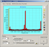
GL's Jitter Measurement application allows one to accurately measure jitter associated with T1 or E1 signals. The jitter evaluation is done by either a tick-by-tick or a cumulative basis. Technically, cumulative jitter is of primary importance as network equipment must cope with the cumulative jitter. However, tick-by-tick measurements are also presented in this module. In addition to these, the application recognizes the very slow variations in a clock signal (below 1 Hz), and the Frequency Offset or Deviations in clock rates.
In addition, GL's Jitter Generation application allows generating jittered output T1/E1 signal with the user-selected frequency and amplitude in compliance with standards such as G.823. In conjunction with GL's Jitter Measurement application, Jitter Generation may be used to test jitter transfer. Jitter transfer measurement is required to confirm that there is no amplification of jitter by network elements (NEs) in the transmission system.
The jitter measurement capability is available in GL's Dual T1/E1 Express (PCIe) boards, tProbe™ T1/E1 Analyzer units, and Universal T1 E1 boards.
GL’s Pulse Shape Measurement software is also available as a part of Jitter Generation and Measurement application. It can determine if the pulse shape fits within a “pulse mask” as specified by standards ITU G.703 and ANSI T1.102-1993.
| GL Communications, Inc. | |
|---|---|
| Product Category | Communications Software |
| Product Number | LTS012 |
| Product Name | Jitter Generation |