Williams Pneumatic Metering Diaphragm Pumps CLD Series

Description
The pneumatic diaphragm metering pump consists of a liquid chamber and an air chamber separated by a diaphragm. In the liquid chamber, the suction (inlet) and discharge (outlet) ports have check valves that control the direction of the fluid flow. A pipe nipple connects the controller to the pump air chamber. In the air chamber, the air/gas power supply from the controller enters and exhausts through the pipe nipple connector. When the controller exhausts the air/gas supply, the liquid suction pressure and the return spring force the diaphragm backwards. The diaphragm stops when the end of the diaphragm stem, which is attached to the air chamber side of the diaphragm, collides with the end of the stroke adjuster. Discharge pressures: Up to100psig (6.9 bar) Materials: 316 ss and TFE liquid ends available. TFE diaphragms for chemical compatibility Duplex option available. Simple Design Easy to Maintain Intrinsic Safety of Pneumatic Operation Stroke Length and Stroke Rate Adjustment High Flow Turndown Corrosion Resistant Construction All 316 SS or TFE Wetted Parts Ease of Installation Recommended for discharge pressures below 100 PSI
Datasheet
Description
The pneumatic diaphragm metering pump consists of a liquid chamber and an air chamber separated by a diaphragm. In the liquid chamber, the suction (inlet) and discharge (outlet) ports have check valves that control the direction of the fluid flow. A pipe nipple connects the controller to the pump air chamber. In the air chamber, the air/gas power supply from the controller enters and exhausts through the pipe nipple connector. When the controller exhausts the air/gas supply, the liquid suction pressure and the return spring force the diaphragm backwards. The diaphragm stops when the end of the diaphragm stem, which is attached to the air chamber side of the diaphragm, collides with the end of the stroke adjuster. Discharge pressures: Up to100psig (6.9 bar) Materials: 316 ss and TFE liquid ends available. TFE diaphragms for chemical compatibility Duplex option available. Simple Design Easy to Maintain Intrinsic Safety of Pneumatic Operation Stroke Length and Stroke Rate Adjustment High Flow Turndown Corrosion Resistant Construction All 316 SS or TFE Wetted Parts Ease of Installation Recommended for discharge pressures below 100 PSI
Datasheet

Suppliers

Company
Product
Description
Supplier Links
Pneumatic Metering Diaphragm Pumps - CLD Series - Williams
Burbank, CA, USA
Pneumatic Metering Diaphragm Pumps
CLD Series
Pneumatic Metering Diaphragm Pumps CLD Series
The pneumatic diaphragm metering pump consists of a liquid chamber and an air chamber separated by a diaphragm. In the liquid chamber, the suction (inlet) and discharge (outlet) ports have check valves that control the direction of the fluid flow. A pipe nipple connects the controller to the pump air chamber. In the air chamber, the air/gas power supply from the controller enters and exhausts through the pipe nipple connector. When the controller exhausts the air/gas supply, the liquid suction pressure and the return spring force the diaphragm backwards. The diaphragm stops when the end of the diaphragm stem, which is attached to the air chamber side of the diaphragm, collides with the end of the stroke adjuster. Discharge pressures: Up to100psig (6.9 bar) Materials: 316 ss and TFE liquid ends available. TFE diaphragms for chemical compatibility Duplex option available. Simple Design Easy to Maintain Intrinsic Safety of Pneumatic Operation Stroke Length and Stroke Rate Adjustment High Flow Turndown Corrosion Resistant Construction All 316 SS or TFE Wetted Parts Ease of Installation Recommended for discharge pressures below 100 PSI
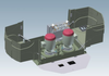
The pneumatic diaphragm metering pump consists of a liquid chamber and an air chamber separated by a diaphragm. In the liquid chamber, the suction (inlet) and discharge (outlet) ports have check valves that control the direction of the fluid flow. A pipe nipple connects the controller to the pump air chamber. In the air chamber, the air/gas power supply from the controller enters and exhausts through the pipe nipple connector. When the controller exhausts the air/gas supply, the liquid suction pressure and the return spring force the diaphragm backwards. The diaphragm stops when the end of the diaphragm stem, which is attached to the air chamber side of the diaphragm, collides with the end of the stroke adjuster.

    • Discharge pressures: Up to100psig (6.9 bar)
    • Materials: 316 ss and TFE liquid ends available.
    • TFE diaphragms for chemical compatibility
    • Duplex option available.
    • Simple Design
    • Easy to Maintain
    • Intrinsic Safety of Pneumatic Operation
    • Stroke Length and Stroke Rate Adjustment
    • High Flow Turndown
    • Corrosion Resistant Construction
    • All 316 SS or TFE Wetted Parts
    • Ease of Installation
    • Recommended for discharge pressures below 100 PSI

Supplier's Site Datasheet

Technical Specifications

  Williams
Product Category Liquid Handling Pumps
Product Number CLD Series
Product Name Pneumatic Metering Diaphragm Pumps
Pump Type Diaphragm Pump; Metering Pump; Positive Displacement Pump
Discharge Pressure 73.0 to 98.0 psi (51.32 to 68.9 m of Water)
Liquid Flow 0.013 to 2.838 GPM (0.05 to 10.75 L/min)
Media Temperature 40 to 185 F (4 to 85 C)
Unlock Full Specs
to access all available technical data

Similar Products

Eco Dosimat - 2.1007.0010 - Metrohm USA, Inc.
Specs
Pump Type Dosing Pump
View Details
Pumps For Operating  1 to 6 Hydraulic Cylinders Synchronously -  - Bansbach Easylift®
Specs
Pump Type Hydraulic Fluid Pump
Power Source Manual (optional feature); DC
Pump Housing Material Aluminum
View Details