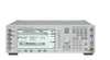
ValueTronics International, Inc. RF Generator E4422A

Description
The E4422A is a 4 GHz RF Generator from Agilent. An RF generator is a tool engineers use to generate sinusoidal outputs while testing electronic equipment. The output will automatically have its frequency varied or swept between frequencies. A “sweep” is one complete cycle of a frequency variation. Engineers use RF signal generators as test equipment, mostly to measure responses of filters, amplifiers, and electrical components. Additional Features: Frequency range: 250 kHz up to 4 GHz Resolution: 0.01 Hz Flexible architecture, upgrade paths for options, and digital 4 GHz electronic attenuator for reliability and repeatability Superior level accuracy Wideband FM and Phase Modulation Step sweep (frequency, power and list) Built-in function generator Frequency Specifications Frequency Range Agilent ESG-4000A: 250 kHz to 4000 MHz Resolution: 0.01 Hz Switching Speed Modulation On: <45 ms, typical Modulation Off: <35 ms, typical Accuracy: Same as timebase Sweep Modes Operating modes Step: frequency & power, and arbitrary list Dwell Time: 2 ms to 60 sec Number of Points: 2 to 401 Internal Reference Oscillator Stability Standard (typical) High Stability (Opt 1E5) Aging Rate <±2 ppm/yr <±0.1 ppm/yr or <± 0.0005 ppm/day after 45 days Temperature <±1 ppm <±0.05 ppm, typical (0° to 55° C) Line Voltage <±0.1 ppm <±0.002 ppm, typical (+5%, -10%) (+5%, -10%) Timebase Reference Output Frequency: 10 MHz Amplitude: >0.35 Vrms into 50 ohm load External Reference Input Frequency: 1, 2, 5, 10 MHz ± typ. 10 ppm Option 1E5: 1 ppm, typical Amplitude: >0.15 Vrms Input Impedance: 50 ohm Output Range 250 kHz to 1000 MHz: +13 to -136 dBm >1000 MHz to 3000 MHz: +10 to -136 dBm >3000 MHz to 4000 MHz: +7 to -136 dBm Resolution 0.02 dB Level Accuracy1 (at 23 ±5°C) +7 to -127 dBm <-127 dBm 250 kHz to 2 GHz: ±0.5 dB ±1.5 dB 2 GHz to 4 GHz: ±0.9 dB ±2.5 dB Attenuator Hold Level Range: >17 dB Switching Speed: <25 ms typical With Power Search Mode: <210 ms typical Reverse Power Protection: 250 kHz to 2000 MHz: 50 Watts >2000 MHz to 4000 MHz: 25 Watts Max DC Voltage: 50 V SWR (typical) 250 kHz to 2000 MHz: <1.4:1 >2000 to 4000 MHz: <1.9:1 Output Impedance: 50 ohms 1Accuracy degrades by 0.02 dB/°C over full temperature range and by 0.3 dB above +7dBm. Frequency Bands Band Frequency Range N# 1 250 kHz to <=249.999 MHz 1 2 >249.999 to <=500 MHz 0.5 3 >500 MHz to <=1 GHz 1 4 >1 to <=2 GHz 2 5 >2 to 4 GHz 4 Spectral Purity SSB Phase Noise (typical,at 20 kHz offset) at 500 MHz: <-120 dBc/Hz at 1000 MHz: <-116 dBc/Hz at 2000 MHz: <- 110 dBc/Hz at 3000 MHz: <-104 dBc/Hz at 4000 MHz: <-104 dBc/Hz Residual FM (CWmode, 0.3-3 kHz BW,CCITT, rms): Phase Noise Mode l: Harmonics <=+4 dBm output level: <-30 dBc Nonharmonics (>3 kHz offset, <+7 dBm output level) 250 kHz to 1000 MHz: <-65 dBc >1000 MHz to 2000 MHz: <-59 dBc >2000 MHz: <-53 dBc Subharmonics <=1000 MHz: None >1000 MHz: <-40 dBc Frequency Modulation Maximum Deviation: N x 10 MHz Resolution: 0.1% of deviation or 1 Hz, whichever is greater Deviation Accuracy (1 kHz rate, dev. Modulation Frequency Response (deviation = 100 kHz) Path Rates 1 dB Bandwidth 3 dB Bandwidth, typical FM1 dc/20 Hz to 100 kHz dc/5 Hz to 10 MHz FM2 dc/20 Hz to 100 kHz dc/5 Hz to 1 MHz Distortion (1 kHz rate, THD, dev. = N x 100 kHz): <1% Phase Modulation Maximum Deviation: N x 90 radians Resolution: 0.1% of set deviation Deviation Accuracy (1 kHz rate): <±(5% of deviation + 0.01 radians) Modulation Frequency Response PM Mode Maximum Rates (3 dB BW) Deviation PM1 PM2 Normal BW N x 90 rad dc to 100 kHz dc to 100 kHz High BW N x 2pi rad dc to 1.5MHz (typ) dc to 1 MHz (typ) N x pi/2 rad dc to 4 MHz (typ) dc to 0.9 MHz (typ) Distortion (1 kHz rate, THD, dev 500 kHz Range (envelope peak <=max specified power): 0 to 100% Resolution: 0.1% Rates (3 dB Bandwidth): dc/10 Hz to 10 kHz Distortion (1 kHz rate, THD) 30% AM: <1.5% 90% AM: <4% Accuracy (1 kHz rate): <±(5% of setting + 1%) Pulse Modulation On/Off Ratio <=3GHz: >80 dB >3 GHz: >60 dB Rise/Fall Times: 150ns, typical Minimum Width (typical) ALC On: 2 μs ALC Off: 0.4 μs Pulse Repetition Frequency (typical) ALC On: 10 Hz to 250 kHz ALC Off: DC to 1.0 MHz Level Accuracy (relative to CW): ± 0.5 dB, typical Internal Pulse Generator (Squarewave only) Squarewave Rate: 0.1 Hz to 50 kHz Pulse Period: 16 μs to 30 seconds Width: 8 μs to 30 seconds Resolution: 4 μs Internal Modulation Source Provides FM, PM, and AM Modulation Signals and LF Out Waveforms: sine, square, ramp, triangle, pulse, noise Rate Range Sine: 0.1 Hz to 50 kHz Square, Ramp, Triangle: 0.1 Hz to 10 kHz Resolution: 0.1 Hz Frequency Accuracy: 0.005% Swept Sine Mode (Frequency, Phase Continuous) Operating Modes: Triggered or Continuous Sweeps Frequency Range: 0.1 Hz to 50 kHz Sweep Time: 1 ms to 65 seconds Resolution: 1 ms Dual Sinewave Mode Frequency Range: 0.1 Hz to 50 kHz Amplitude Ratio: 0 to 100% Amplitude Resolution: 0.1% LF Out (Internal Modulation Source) Amplitude: 0 to 3 Vpeak into 50 ohms Output Impedance: <1 ohm External Modulation Inputs Modulation Types: Ext1: FM, PM, AM, and Burst Envelope Ext2: FM, PM, AM, and Pulse Simultaneous Modulation All modulation types may be simultaneously enabled, except: FM with PM, AM with Burst envelope. AM, FM, and PM can sum simultaneous inputs from any two sources (INT, EXT1, and EXT2.) Any given source (INT, EXT1, or EXT2) may only be routed to one activated modulation type. Remote Programming Interface: HP-IB (IEEE-488.2-1987) with Listen and Talk, RS-232 Control Languages: SCPI version 1992.0, also compatible with Agilent 8656B & 8657A/B/D/J mnemonics Functions Controlled: All front panel functions except power switch and knobs IEEE-488 Functions: SH1, AH1, T6, TE0, L4, LE0, SR1, RL1, PP0, DC1, DT0, C0, E2 General Power Requirements: 90 to 254 V; 50,60, or 400 Hz; 200 W maximum Operating Temperature Range: 0 to 55° C Leakage: Conducted and radiated interference meets MIL-STD-461B RE02 Part 2 and CISPR 11 Storage Registers: Up to 100 storage registers, up to 10 sequences available Dimensions: 133 mm H x 426 mm W x 432 mm D (5.25 in H x 16.8 in W x 17 in D) The Agilent E4422A Signal generator offers excellent in-channel performance with superior quality and reliability. The first in a new generation of signal generators, it provides excellent frequency and level control, and wide modulation capabilities. The E4422A is ideally suited to meet the demanding requirements of today's receiver test, component test and local oscillator applications. The innovative design of the Agilent E4422A provides a flexible architecture that can be tailored to meet the changing demands of evolving markets. Lower initial cost, high reliability and a two-year calibration cycle, all strive to minimize the cost of ownership. The Agilent E4422A RF signal generator is designed for long-term dependability, which maximizes production throughput and uptime.
Datasheet
Description
The E4422A is a 4 GHz RF Generator from Agilent. An RF generator is a tool engineers use to generate sinusoidal outputs while testing electronic equipment. The output will automatically have its frequency varied or swept between frequencies. A “sweep” is one complete cycle of a frequency variation. Engineers use RF signal generators as test equipment, mostly to measure responses of filters, amplifiers, and electrical components. Additional Features: Frequency range: 250 kHz up to 4 GHz Resolution: 0.01 Hz Flexible architecture, upgrade paths for options, and digital 4 GHz electronic attenuator for reliability and repeatability Superior level accuracy Wideband FM and Phase Modulation Step sweep (frequency, power and list) Built-in function generator Frequency Specifications Frequency Range Agilent ESG-4000A: 250 kHz to 4000 MHz Resolution: 0.01 Hz Switching Speed Modulation On: <45 ms, typical Modulation Off: <35 ms, typical Accuracy: Same as timebase Sweep Modes Operating modes Step: frequency & power, and arbitrary list Dwell Time: 2 ms to 60 sec Number of Points: 2 to 401 Internal Reference Oscillator Stability Standard (typical) High Stability (Opt 1E5) Aging Rate <±2 ppm/yr <±0.1 ppm/yr or <± 0.0005 ppm/day after 45 days Temperature <±1 ppm <±0.05 ppm, typical (0° to 55° C) Line Voltage <±0.1 ppm <±0.002 ppm, typical (+5%, -10%) (+5%, -10%) Timebase Reference Output Frequency: 10 MHz Amplitude: >0.35 Vrms into 50 ohm load External Reference Input Frequency: 1, 2, 5, 10 MHz ± typ. 10 ppm Option 1E5: 1 ppm, typical Amplitude: >0.15 Vrms Input Impedance: 50 ohm Output Range 250 kHz to 1000 MHz: +13 to -136 dBm >1000 MHz to 3000 MHz: +10 to -136 dBm >3000 MHz to 4000 MHz: +7 to -136 dBm Resolution 0.02 dB Level Accuracy1 (at 23 ±5°C) +7 to -127 dBm <-127 dBm 250 kHz to 2 GHz: ±0.5 dB ±1.5 dB 2 GHz to 4 GHz: ±0.9 dB ±2.5 dB Attenuator Hold Level Range: >17 dB Switching Speed: <25 ms typical With Power Search Mode: <210 ms typical Reverse Power Protection: 250 kHz to 2000 MHz: 50 Watts >2000 MHz to 4000 MHz: 25 Watts Max DC Voltage: 50 V SWR (typical) 250 kHz to 2000 MHz: <1.4:1 >2000 to 4000 MHz: <1.9:1 Output Impedance: 50 ohms 1Accuracy degrades by 0.02 dB/°C over full temperature range and by 0.3 dB above +7dBm. Frequency Bands Band Frequency Range N# 1 250 kHz to <=249.999 MHz 1 2 >249.999 to <=500 MHz 0.5 3 >500 MHz to <=1 GHz 1 4 >1 to <=2 GHz 2 5 >2 to 4 GHz 4 Spectral Purity SSB Phase Noise (typical,at 20 kHz offset) at 500 MHz: <-120 dBc/Hz at 1000 MHz: <-116 dBc/Hz at 2000 MHz: <- 110 dBc/Hz at 3000 MHz: <-104 dBc/Hz at 4000 MHz: <-104 dBc/Hz Residual FM (CWmode, 0.3-3 kHz BW,CCITT, rms): Phase Noise Mode l: Harmonics <=+4 dBm output level: <-30 dBc Nonharmonics (>3 kHz offset, <+7 dBm output level) 250 kHz to 1000 MHz: <-65 dBc >1000 MHz to 2000 MHz: <-59 dBc >2000 MHz: <-53 dBc Subharmonics <=1000 MHz: None >1000 MHz: <-40 dBc Frequency Modulation Maximum Deviation: N x 10 MHz Resolution: 0.1% of deviation or 1 Hz, whichever is greater Deviation Accuracy (1 kHz rate, dev. Modulation Frequency Response (deviation = 100 kHz) Path Rates 1 dB Bandwidth 3 dB Bandwidth, typical FM1 dc/20 Hz to 100 kHz dc/5 Hz to 10 MHz FM2 dc/20 Hz to 100 kHz dc/5 Hz to 1 MHz Distortion (1 kHz rate, THD, dev. = N x 100 kHz): <1% Phase Modulation Maximum Deviation: N x 90 radians Resolution: 0.1% of set deviation Deviation Accuracy (1 kHz rate): <±(5% of deviation + 0.01 radians) Modulation Frequency Response PM Mode Maximum Rates (3 dB BW) Deviation PM1 PM2 Normal BW N x 90 rad dc to 100 kHz dc to 100 kHz High BW N x 2pi rad dc to 1.5MHz (typ) dc to 1 MHz (typ) N x pi/2 rad dc to 4 MHz (typ) dc to 0.9 MHz (typ) Distortion (1 kHz rate, THD, dev 500 kHz Range (envelope peak <=max specified power): 0 to 100% Resolution: 0.1% Rates (3 dB Bandwidth): dc/10 Hz to 10 kHz Distortion (1 kHz rate, THD) 30% AM: <1.5% 90% AM: <4% Accuracy (1 kHz rate): <±(5% of setting + 1%) Pulse Modulation On/Off Ratio <=3GHz: >80 dB >3 GHz: >60 dB Rise/Fall Times: 150ns, typical Minimum Width (typical) ALC On: 2 μs ALC Off: 0.4 μs Pulse Repetition Frequency (typical) ALC On: 10 Hz to 250 kHz ALC Off: DC to 1.0 MHz Level Accuracy (relative to CW): ± 0.5 dB, typical Internal Pulse Generator (Squarewave only) Squarewave Rate: 0.1 Hz to 50 kHz Pulse Period: 16 μs to 30 seconds Width: 8 μs to 30 seconds Resolution: 4 μs Internal Modulation Source Provides FM, PM, and AM Modulation Signals and LF Out Waveforms: sine, square, ramp, triangle, pulse, noise Rate Range Sine: 0.1 Hz to 50 kHz Square, Ramp, Triangle: 0.1 Hz to 10 kHz Resolution: 0.1 Hz Frequency Accuracy: 0.005% Swept Sine Mode (Frequency, Phase Continuous) Operating Modes: Triggered or Continuous Sweeps Frequency Range: 0.1 Hz to 50 kHz Sweep Time: 1 ms to 65 seconds Resolution: 1 ms Dual Sinewave Mode Frequency Range: 0.1 Hz to 50 kHz Amplitude Ratio: 0 to 100% Amplitude Resolution: 0.1% LF Out (Internal Modulation Source) Amplitude: 0 to 3 Vpeak into 50 ohms Output Impedance: <1 ohm External Modulation Inputs Modulation Types: Ext1: FM, PM, AM, and Burst Envelope Ext2: FM, PM, AM, and Pulse Simultaneous Modulation All modulation types may be simultaneously enabled, except: FM with PM, AM with Burst envelope. AM, FM, and PM can sum simultaneous inputs from any two sources (INT, EXT1, and EXT2.) Any given source (INT, EXT1, or EXT2) may only be routed to one activated modulation type. Remote Programming Interface: HP-IB (IEEE-488.2-1987) with Listen and Talk, RS-232 Control Languages: SCPI version 1992.0, also compatible with Agilent 8656B & 8657A/B/D/J mnemonics Functions Controlled: All front panel functions except power switch and knobs IEEE-488 Functions: SH1, AH1, T6, TE0, L4, LE0, SR1, RL1, PP0, DC1, DT0, C0, E2 General Power Requirements: 90 to 254 V; 50,60, or 400 Hz; 200 W maximum Operating Temperature Range: 0 to 55° C Leakage: Conducted and radiated interference meets MIL-STD-461B RE02 Part 2 and CISPR 11 Storage Registers: Up to 100 storage registers, up to 10 sequences available Dimensions: 133 mm H x 426 mm W x 432 mm D (5.25 in H x 16.8 in W x 17 in D) The Agilent E4422A Signal generator offers excellent in-channel performance with superior quality and reliability. The first in a new generation of signal generators, it provides excellent frequency and level control, and wide modulation capabilities. The E4422A is ideally suited to meet the demanding requirements of today's receiver test, component test and local oscillator applications. The innovative design of the Agilent E4422A provides a flexible architecture that can be tailored to meet the changing demands of evolving markets. Lower initial cost, high reliability and a two-year calibration cycle, all strive to minimize the cost of ownership. The Agilent E4422A RF signal generator is designed for long-term dependability, which maximizes production throughput and uptime.
Datasheet

Suppliers

Company
Product
Description
Supplier Links
RF Generator E4422A
The E4422A is a 4 GHz RF Generator from Agilent. An RF generator is a tool engineers use to generate sinusoidal outputs while testing electronic equipment. The output will automatically have its frequency varied or swept between frequencies. A “sweep” is one complete cycle of a frequency variation. Engineers use RF signal generators as test equipment, mostly to measure responses of filters, amplifiers, and electrical components. Additional Features: Frequency range: 250 kHz up to 4 GHz Resolution: 0.01 Hz Flexible architecture, upgrade paths for options, and digital 4 GHz electronic attenuator for reliability and repeatability Superior level accuracy Wideband FM and Phase Modulation Step sweep (frequency, power and list) Built-in function generator Frequency Specifications Frequency Range Agilent ESG-4000A: 250 kHz to 4000 MHz Resolution: 0.01 Hz Switching Speed Modulation On: <45 ms, typical Modulation Off: <35 ms, typical Accuracy: Same as timebase Sweep Modes Operating modes Step: frequency & power, and arbitrary list Dwell Time: 2 ms to 60 sec Number of Points: 2 to 401 Internal Reference Oscillator Stability Standard (typical) High Stability (Opt 1E5) Aging Rate <±2 ppm/yr <±0.1 ppm/yr or <± 0.0005 ppm/day after 45 days Temperature <±1 ppm <±0.05 ppm, typical (0° to 55° C) Line Voltage <±0.1 ppm <±0.002 ppm, typical (+5%, -10%) (+5%, -10%) Timebase Reference Output Frequency: 10 MHz Amplitude: >0.35 Vrms into 50 ohm load External Reference Input Frequency: 1, 2, 5, 10 MHz ± typ. 10 ppm Option 1E5: 1 ppm, typical Amplitude: >0.15 Vrms Input Impedance: 50 ohm Output Range 250 kHz to 1000 MHz: +13 to -136 dBm >1000 MHz to 3000 MHz: +10 to -136 dBm >3000 MHz to 4000 MHz: +7 to -136 dBm Resolution 0.02 dB Level Accuracy1 (at 23 ±5°C) +7 to -127 dBm <-127 dBm 250 kHz to 2 GHz: ±0.5 dB ±1.5 dB 2 GHz to 4 GHz: ±0.9 dB ±2.5 dB Attenuator Hold Level Range: >17 dB Switching Speed: <25 ms typical With Power Search Mode: <210 ms typical Reverse Power Protection: 250 kHz to 2000 MHz: 50 Watts >2000 MHz to 4000 MHz: 25 Watts Max DC Voltage: 50 V SWR (typical) 250 kHz to 2000 MHz: <1.4:1 >2000 to 4000 MHz: <1.9:1 Output Impedance: 50 ohms 1Accuracy degrades by 0.02 dB/°C over full temperature range and by 0.3 dB above +7dBm. Frequency Bands Band Frequency Range N# 1 250 kHz to <=249.999 MHz 1 2 >249.999 to <=500 MHz 0.5 3 >500 MHz to <=1 GHz 1 4 >1 to <=2 GHz 2 5 >2 to 4 GHz 4 Spectral Purity SSB Phase Noise (typical,at 20 kHz offset) at 500 MHz: <-120 dBc/Hz at 1000 MHz: <-116 dBc/Hz at 2000 MHz: <- 110 dBc/Hz at 3000 MHz: <-104 dBc/Hz at 4000 MHz: <-104 dBc/Hz Residual FM (CWmode, 0.3-3 kHz BW,CCITT, rms): Phase Noise Mode l: Harmonics <=+4 dBm output level: <-30 dBc Nonharmonics (>3 kHz offset, <+7 dBm output level) 250 kHz to 1000 MHz: <-65 dBc >1000 MHz to 2000 MHz: <-59 dBc >2000 MHz: <-53 dBc Subharmonics <=1000 MHz: None >1000 MHz: <-40 dBc Frequency Modulation Maximum Deviation: N x 10 MHz Resolution: 0.1% of deviation or 1 Hz, whichever is greater Deviation Accuracy (1 kHz rate, dev. Modulation Frequency Response (deviation = 100 kHz) Path Rates 1 dB Bandwidth 3 dB Bandwidth, typical FM1 dc/20 Hz to 100 kHz dc/5 Hz to 10 MHz FM2 dc/20 Hz to 100 kHz dc/5 Hz to 1 MHz Distortion (1 kHz rate, THD, dev. = N x 100 kHz): <1% Phase Modulation Maximum Deviation: N x 90 radians Resolution: 0.1% of set deviation Deviation Accuracy (1 kHz rate): <±(5% of deviation + 0.01 radians) Modulation Frequency Response PM Mode Maximum Rates (3 dB BW) Deviation PM1 PM2 Normal BW N x 90 rad dc to 100 kHz dc to 100 kHz High BW N x 2pi rad dc to 1.5MHz (typ) dc to 1 MHz (typ) N x pi/2 rad dc to 4 MHz (typ) dc to 0.9 MHz (typ) Distortion (1 kHz rate, THD, dev 500 kHz Range (envelope peak <=max specified power): 0 to 100% Resolution: 0.1% Rates (3 dB Bandwidth): dc/10 Hz to 10 kHz Distortion (1 kHz rate, THD) 30% AM: <1.5% 90% AM: <4% Accuracy (1 kHz rate): <±(5% of setting + 1%) Pulse Modulation On/Off Ratio <=3GHz: >80 dB >3 GHz: >60 dB Rise/Fall Times: 150ns, typical Minimum Width (typical) ALC On: 2 μs ALC Off: 0.4 μs Pulse Repetition Frequency (typical) ALC On: 10 Hz to 250 kHz ALC Off: DC to 1.0 MHz Level Accuracy (relative to CW): ± 0.5 dB, typical Internal Pulse Generator (Squarewave only) Squarewave Rate: 0.1 Hz to 50 kHz Pulse Period: 16 μs to 30 seconds Width: 8 μs to 30 seconds Resolution: 4 μs Internal Modulation Source Provides FM, PM, and AM Modulation Signals and LF Out Waveforms: sine, square, ramp, triangle, pulse, noise Rate Range Sine: 0.1 Hz to 50 kHz Square, Ramp, Triangle: 0.1 Hz to 10 kHz Resolution: 0.1 Hz Frequency Accuracy: 0.005% Swept Sine Mode (Frequency, Phase Continuous) Operating Modes: Triggered or Continuous Sweeps Frequency Range: 0.1 Hz to 50 kHz Sweep Time: 1 ms to 65 seconds Resolution: 1 ms Dual Sinewave Mode Frequency Range: 0.1 Hz to 50 kHz Amplitude Ratio: 0 to 100% Amplitude Resolution: 0.1% LF Out (Internal Modulation Source) Amplitude: 0 to 3 Vpeak into 50 ohms Output Impedance: <1 ohm External Modulation Inputs Modulation Types: Ext1: FM, PM, AM, and Burst Envelope Ext2: FM, PM, AM, and Pulse Simultaneous Modulation All modulation types may be simultaneously enabled, except: FM with PM, AM with Burst envelope. AM, FM, and PM can sum simultaneous inputs from any two sources (INT, EXT1, and EXT2.) Any given source (INT, EXT1, or EXT2) may only be routed to one activated modulation type. Remote Programming Interface: HP-IB (IEEE-488.2-1987) with Listen and Talk, RS-232 Control Languages: SCPI version 1992.0, also compatible with Agilent 8656B & 8657A/B/D/J mnemonics Functions Controlled: All front panel functions except power switch and knobs IEEE-488 Functions: SH1, AH1, T6, TE0, L4, LE0, SR1, RL1, PP0, DC1, DT0, C0, E2 General Power Requirements: 90 to 254 V; 50,60, or 400 Hz; 200 W maximum Operating Temperature Range: 0 to 55° C Leakage: Conducted and radiated interference meets MIL-STD-461B RE02 Part 2 and CISPR 11 Storage Registers: Up to 100 storage registers, up to 10 sequences available Dimensions: 133 mm H x 426 mm W x 432 mm D (5.25 in H x 16.8 in W x 17 in D) The Agilent E4422A Signal generator offers excellent in-channel performance with superior quality and reliability. The first in a new generation of signal generators, it provides excellent frequency and level control, and wide modulation capabilities. The E4422A is ideally suited to meet the demanding requirements of today's receiver test, component test and local oscillator applications. The innovative design of the Agilent E4422A provides a flexible architecture that can be tailored to meet the changing demands of evolving markets. Lower initial cost, high reliability and a two-year calibration cycle, all strive to minimize the cost of ownership. The Agilent E4422A RF signal generator is designed for long-term dependability, which maximizes production throughput and uptime.

The E4422A is a 4 GHz RF Generator from Agilent. An RF generator is a tool engineers use to generate sinusoidal outputs while testing electronic equipment. The output will automatically have its frequency varied or swept between frequencies. A “sweep” is one complete cycle of a frequency variation. Engineers use RF signal generators as test equipment, mostly to measure responses of filters, amplifiers, and electrical components.

Additional Features:

  • Frequency range: 250 kHz up to 4 GHz
  • Resolution: 0.01 Hz
  • Flexible architecture, upgrade paths for options, and digital
  • 4 GHz electronic attenuator for reliability and repeatability
  • Superior level accuracy
  • Wideband FM and Phase Modulation
  • Step sweep (frequency, power and list)
  • Built-in function generator

Frequency Specifications

  • Frequency Range Agilent ESG-4000A: 250 kHz to 4000 MHz
  • Resolution: 0.01 Hz
  • Switching Speed Modulation On: <45 ms, typical Modulation Off: <35 ms, typical
  • Accuracy: Same as timebase Sweep Modes
  • Operating modes Step: frequency & power, and arbitrary list
  • Dwell Time: 2 ms to 60 sec
  • Number of Points: 2 to 401 Internal Reference Oscillator
  • Stability Standard (typical) High Stability (Opt 1E5) Aging Rate <±2 ppm/yr <±0.1 ppm/yr or <± 0.0005 ppm/day after 45 days
  • Temperature <±1 ppm <±0.05 ppm, typical (0° to 55° C)
  • Line Voltage <±0.1 ppm <±0.002 ppm, typical (+5%, -10%) (+5%, -10%)
  • Timebase Reference Output Frequency: 10 MHz Amplitude: >0.35 Vrms into 50 ohm load
  • External Reference Input Frequency: 1, 2, 5, 10 MHz ± typ. 10 ppm Option 1E5: 1 ppm, typical Amplitude: >0.15
  • Vrms Input Impedance: 50 ohm Output
  • Range 250 kHz to 1000 MHz: +13 to -136 dBm >1000 MHz to 3000 MHz: +10 to -136 dBm >3000 MHz to 4000
  • MHz: +7 to -136 dBm
  • Resolution 0.02 dB
  • Level Accuracy1 (at 23 ±5°C) +7 to -127 dBm <-127 dBm 250 kHz to 2 GHz: ±0.5 dB ±1.5 dB
  • 2 GHz to 4 GHz: ±0.9 dB ±2.5 dB
  • Attenuator Hold Level Range: >17 dB
  • Switching Speed: <25 ms typical With Power Search Mode: <210 ms typical
  • Reverse Power Protection: 250 kHz to 2000 MHz: 50 Watts >2000 MHz to 4000 MHz: 25 Watts Max DC Voltage: 50 V
  • SWR (typical) 250 kHz to 2000 MHz: <1.4:1 >2000 to 4000 MHz: <1.9:1
  • Output Impedance: 50 ohms 1Accuracy degrades by 0.02 dB/°C over full temperature range and by 0.3 dB above +7dBm.

Frequency Bands

  • Band Frequency Range N# 1 250 kHz to <=249.999 MHz 1 2 >249.999 to <=500 MHz 0.5 3 >500 MHz to <=1 GHz 1 4 >1 to <=2 GHz 2 5 >2 to 4 GHz 4

Spectral Purity

  • SSB Phase Noise (typical,at 20 kHz offset) at 500 MHz: <-120 dBc/Hz at 1000 MHz: <-116 dBc/Hz at 2000 MHz: <-
  • 110 dBc/Hz at 3000 MHz: <-104 dBc/Hz at 4000 MHz: <-104 dBc/Hz
  • Residual FM (CWmode, 0.3-3 kHz BW,CCITT, rms): Phase Noise Mode l: <N x 2 Hz Phase Noise Mode 2: <N x 4 Hz
  • Harmonics <=+4 dBm output level: <-30 dBc
  • Nonharmonics (>3 kHz offset, <+7 dBm output level) 250 kHz to 1000 MHz: <-65 dBc >1000 MHz to 2000 MHz: <-59 dBc >2000 MHz: <-53 dBc
  • Subharmonics <=1000 MHz: None >1000 MHz: <-40 dBc

Frequency Modulation

  • Maximum Deviation: N x 10 MHz
  • Resolution: 0.1% of deviation or 1 Hz, whichever is greater
  • Deviation Accuracy (1 kHz rate, dev. <N x 100 kHz): <±(3.5% of FM deviation + 20 Hz)
  • Modulation Frequency Response (deviation = 100 kHz)
  • Path Rates 1 dB Bandwidth 3 dB Bandwidth, typical FM1 dc/20 Hz to 100 kHz dc/5 Hz to 10 MHz
  • FM2 dc/20 Hz to 100 kHz dc/5 Hz to 1 MHz
  • Distortion (1 kHz rate, THD, dev. = N x 100 kHz): <1%

Phase Modulation

  • Maximum Deviation: N x 90 radians
  • Resolution: 0.1% of set deviation
  • Deviation Accuracy (1 kHz rate): <±(5% of deviation + 0.01 radians)
  • Modulation Frequency Response
  • PM Mode Maximum Rates (3 dB BW) Deviation PM1 PM2 Normal BW N x 90 rad dc to 100 kHz dc to 100 kHz
  • High BW N x 2pi rad dc to 1.5MHz (typ) dc to 1 MHz (typ) N x pi/2 rad dc to 4 MHz (typ) dc to 0.9 MHz (typ)
  • Distortion (1 kHz rate, THD, dev <N x 90 rad): <1% Amplitude Modulation fc>500 kHz
  • Range (envelope peak <=max specified power): 0 to 100%
  • Resolution: 0.1% Rates (3 dB Bandwidth): dc/10 Hz to 10 kHz
  • Distortion (1 kHz rate, THD) 30% AM: <1.5% 90% AM: <4%
  • Accuracy (1 kHz rate): <±(5% of setting + 1%)

Pulse Modulation

  • On/Off Ratio <=3GHz: >80 dB >3 GHz: >60 dB
  • Rise/Fall Times: 150ns, typical
  • Minimum Width (typical) ALC On: 2 μs ALC Off: 0.4 μs
  • Pulse Repetition Frequency (typical) ALC On: 10 Hz to 250 kHz ALC Off: DC to 1.0 MHz
  • Level Accuracy (relative to CW): ± 0.5 dB, typical
  • Internal Pulse Generator (Squarewave only) Squarewave Rate: 0.1 Hz to 50 kHz Pulse Period: 16 μs to 30 seconds
  • Width: 8 μs to 30 seconds Resolution: 4 μs Internal Modulation Source Provides FM, PM, and AM Modulation Signals and LF Out
  • Waveforms: sine, square, ramp, triangle, pulse, noise
  • Rate Range Sine: 0.1 Hz to 50 kHz Square, Ramp, Triangle: 0.1 Hz to 10 kHz
  • Resolution: 0.1 Hz
  • Frequency Accuracy: 0.005%
  • Swept Sine Mode (Frequency, Phase Continuous)
  • Operating Modes: Triggered or Continuous Sweeps
  • Frequency Range: 0.1 Hz to 50 kHz
  • Sweep Time: 1 ms to 65 seconds
  • Resolution: 1 ms
  • Dual Sinewave Mode Frequency Range: 0.1 Hz to 50 kHz
  • Amplitude Ratio: 0 to 100%
  • Amplitude Resolution: 0.1% LF Out (Internal Modulation Source)
  • Amplitude: 0 to 3 Vpeak into 50 ohms
  • Output Impedance: <1 ohm External Modulation Inputs
  • Modulation Types: Ext1: FM, PM, AM, and Burst Envelope Ext2: FM, PM, AM, and Pulse
  • Simultaneous Modulation All modulation types may be simultaneously enabled, except: FM with PM, AM with Burst envelope. AM, FM, and PM can sum simultaneous inputs from any two sources (INT, EXT1, and EXT2.) Any given source (INT, EXT1, or EXT2) may only be routed to one activated modulation type.

Remote Programming

  • Interface: HP-IB (IEEE-488.2-1987) with Listen and Talk, RS-232
  • Control Languages: SCPI version 1992.0, also compatible with Agilent 8656B & 8657A/B/D/J mnemonics
  • Functions Controlled: All front panel functions except power switch and knobs
  • IEEE-488 Functions: SH1, AH1, T6, TE0, L4, LE0, SR1, RL1, PP0, DC1, DT0, C0, E2

General

  • Power Requirements: 90 to 254 V; 50,60, or 400 Hz; 200 W maximum
  • Operating Temperature Range: 0 to 55° C
  • Leakage: Conducted and radiated interference meets MIL-STD-461B RE02 Part 2 and CISPR 11
  • Storage Registers: Up to 100 storage registers, up to 10 sequences available
  • Dimensions: 133 mm H x 426 mm W x 432 mm D (5.25 in H x 16.8 in W x 17 in D)

The Agilent E4422A Signal generator offers excellent in-channel performance with superior quality and reliability. The first in a new generation of signal generators, it provides excellent frequency and level control, and wide modulation capabilities. The E4422A is ideally suited to meet the demanding requirements of today's receiver test, component test and local oscillator applications.

The innovative design of the Agilent E4422A provides a flexible architecture that can be tailored to meet the changing demands of evolving markets. Lower initial cost, high reliability and a two-year calibration cycle, all strive to minimize the cost of ownership. The Agilent E4422A RF signal generator is designed for long-term dependability, which maximizes production throughput and uptime.
Supplier's Site Datasheet

Technical Specifications

  ValueTronics International, Inc.
Product Category Signal Generators
Product Number E4422A
Product Name RF Generator
Device Type Generator
Unlock Full Specs
to access all available technical data

Similar Products

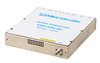
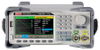
RF Generator - SSG3021X-IQE - Siglent Technologies NA, Inc.
Siglent Technologies NA, Inc.
Specs
Device Type Generator
Generator Type Signal; RF
Form Factor Portable
View Details
9kHz to 40GHz Low Phase Noise Signal Generator Module - MSG9K40G - Corech Microwave
Specs
Device Type Generator
Generator Type Pulse
Form Factor Other Form Factor
View Details
UTG4122A 120MHz 2Ch Performance-Series Arbitrary Waveform Generator - UTG4122A - Uni-Trend US
Specs
Interface Universal Serial Bus; USB, LAN, 10MHz In/Out, Trigger, Mod In, Cnt
Inputs 2
Minimum 120 MHz
View Details