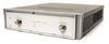
The 8513A is a test set from Agilent. An electronic equipment test set is the tool engineers use for easy, accurate characterization of radiofrequency components. These test sets are devices that enable the measurement of important electronic parameters, displaying them clearly on easy-to-read defined displays.
Additional Features:
45 MHz to 26.5 GHz Reflection Transmission test set
One bridge for making reflection (S11) and transmission (S21) measurements
Three RF to IF converters
No step attenuators to internally change the incident power level
No bias tees to apply external DC bias to the test poort center conductors
Test Ports (Front Panel)
Connector Type: precision 3.5 mm male
Impedance: 540 ohms nominal
Damage input level: Port 1: >+20 dBm; Port 2: >+13 dBm
Nominal connector size: 20 mm
Recommended torque: 90 n-cm
Nominal operating power level:
0.045 to 8 GHz: -5dBm
8 to 20 GHz: -10 dBm
20 to 26.5 GHz: -25 dBm
RF Input Connector (Rear Panel)
Connector type: precision 3.5 mm female
Damage input level: +23 dBm
Source power levels for reference channel phase lock: Minimum: -2 dBm; Maximum: +12 dBm
Nominal connector nut size: 8 mm
Recommended torque: Precision 3.5mm: 90 n-cm; SMA: 56 n-cm
Power requirements and Physical Characteristics
Operating temperature: 0°C to 55°C
Power: 110, 120, 220 or 240 ±10% Vac; 47 to 66 Hz line frequency
Dimensions: 460 mm x 133 mm x 610 mm (18.1 x 5.25 x 24 inches)
The 8513A is designed to operate specifically with the Agilent 8510 network analyzer. The combination of the Agilent 8513A Test Set with the Agilent 8510 network analyzer and source provides a system for making S-parameter measurements over the frequency range of 45 MHz to 26.5 GHz. This system is suited for making all four S-parameter measurements on two port devices without physically reversing the DUT (device under test).
The 8513A is a test set from Agilent. An electronic equipment test set is the tool engineers use for easy, accurate characterization of radiofrequency components. These test sets are devices that enable the measurement of important electronic parameters, displaying them clearly on easy-to-read defined displays.
Additional Features:
- 45 MHz to 26.5 GHz Reflection Transmission test set
- One bridge for making reflection (S11) and transmission (S21) measurements
- Three RF to IF converters
- No step attenuators to internally change the incident power level
- No bias tees to apply external DC bias to the test poort center conductors
Test Ports (Front Panel)
- Connector Type: precision 3.5 mm male
- Impedance: 540 ohms nominal
- Damage input level: Port 1: >+20 dBm; Port 2: >+13 dBm
- Nominal connector size: 20 mm
- Recommended torque: 90 n-cm
Nominal operating power level:
- 0.045 to 8 GHz: -5dBm
- 8 to 20 GHz: -10 dBm
- 20 to 26.5 GHz: -25 dBm
RF Input Connector (Rear Panel)
- Connector type: precision 3.5 mm female
- Damage input level: +23 dBm
- Source power levels for reference channel phase lock: Minimum: -2 dBm; Maximum: +12 dBm
- Nominal connector nut size: 8 mm
- Recommended torque: Precision 3.5mm: 90 n-cm; SMA: 56 n-cm
Power requirements and Physical Characteristics
- Operating temperature: 0°C to 55°C
- Power: 110, 120, 220 or 240 ±10% Vac; 47 to 66 Hz line frequency
- Dimensions: 460 mm x 133 mm x 610 mm (18.1 x 5.25 x 24 inches)
The 8513A is designed to operate specifically with the Agilent 8510 network analyzer. The combination of the Agilent 8513A Test Set with the Agilent 8510 network analyzer and source provides a system for making S-parameter measurements over the frequency range of 45 MHz to 26.5 GHz. This system is suited for making all four S-parameter measurements on two port devices without physically reversing the DUT (device under test).