
For documentation and other MARK II models, please see our MARK II Marketing Page.
Technical Features
Model Specific
Adjustment Type:
Connection Type:
Housing Type:
Optical Block:
LED Light Source
Sensing Range:
Family Specific
Supply Voltage:
Current Requirements:
Output Transistors:
Response Time
Hysteresis:
Indicators:
Light Immunity:
Ambient Temperature:
Rugged Construction:
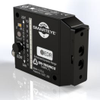
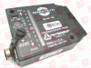
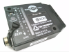
PHOTOELECTRIC SENSOR, SMARTEYE, MARK II, WITH INFRARED LED, POTENTIOMETER ADJUSTMENT, 4-WIRE, M12 CONNECTOR, F1 FIBEROPTIC OPTICAL BLOCK, 12-24 VDC SUPPLY VOLTAGE, POLARITY PROTECTED. FREE 2 YEAR RADWELL WARRANTY
TRI-TRONICS Sensors & Switches SEIF1
| Tri-Tronics Company, Inc. | Radwell International | |
|---|---|---|
| Product Category | Photoelectric Sensors | Photoelectric Sensors |
| Product Number | SEIF1 | 574981 |
| Product Name | SMARTYEYE ® MARK II with Infrared LED, potentiometer adjustment, 4-wire M12 Connector and F1 Fiberoptic Optical Block | Photoelectric |
| Body Shape | Rectangular | |
| Operation Distance | 42 inch (1067 mm) | |
| Operating Temperature | -40 to 158 F (-40 to 70 C) | |
| Beam Type | Infrared |