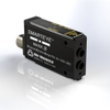
Tri-Tronics Company, Inc. SMARTYEYE ® MARK III with Red LED, 4-wire M12 Connector SE3RC

Description
For documentation and other MARK III models, please see our MARK III Marketing Page. Technical Features Model Specific Adjustment Type: Potentiometer Connection Type: Connector, 4-pin M12 Housing Type: DIN Rail Optical Block: None. LED Light Source Red = 660nm Best choice for use with plastic fiberoptic light guides. Useful when sensing translucent objects in proximity (Beam Make) mode. Useful when sensing transparent objects in fiberoptic retroreflective (Beam Break) mode. Can be polarized for retroreflective (Beam Break) sensing to reduce proxing on shiny objects. Opposed fiberoptic light guides can be polarized for sensing some translucent plastic containers; consult factory for details. Used as red filter for color perception advantages. Sensing Range: Depends on Optical Block Family Specific Supply Voltage: 12 to 24 VDC Polarity Protected Current Requirements: 85mA (exclusive of load) Output Transistors: (1) NPN and (1) PNP sensor output transistor NPN Sink up to 150mA PNP Source up to 150mA Momentary short circuit protected Outputs protected from pulsing during power up Light/dark switch de4termines output status Light = Light "ON" operate Dark = Dark "ON" operate Response Time Minimum duration of input event Light state response = 50 microseconds Dark state response = 140 microseconds Leading edge variation less than 20 microseconds Hysteresis: Less than 400 millivolts for maximum sensitivity and resolution Light Immunity: Responds to sensor’s pulse modulated light source Immune to most ambient light Ambient Temperature: -40°C to 70°C (-40°F to158°F) Indicators: OUTPUT INDICATOR – RED LED illuminates when the output transistors are in the “ON” state as determined by the position of the Light/Dark switch BEAM STATUS INDICATOR – RED LED illuminates when returned light level exceeds “5” on the CONTRAST INDICATOR EDR® INDICATOR – Intensity of GREEN LED provides indication of where in the dynamic operating range the OFFSET/EDR® adjustment has been set CONTRAST INDICATOR – Displays scaled reading of sensor’s response to contrasting light levels (light vs. dark) on a 10 bar LED display OFFSET/EDR® Adjustment: Sets initial level on CONTRAST INDICATOR in relation to mid-scale switch point of 5 – functions as sensitivity adjustment Controls Enhanced Dynamic Range circuit (EDR®) which functions to avoid saturation Rugged Construction: Chemical resistant, high-impact polycarbonate housing Waterproof, NEMA 4X, 6P and IP67 enclosure ratings Epoxy encapsulated for mechanical strength
Datasheet
Description
For documentation and other MARK III models, please see our MARK III Marketing Page. Technical Features Model Specific Adjustment Type: Potentiometer Connection Type: Connector, 4-pin M12 Housing Type: DIN Rail Optical Block: None. LED Light Source Red = 660nm Best choice for use with plastic fiberoptic light guides. Useful when sensing translucent objects in proximity (Beam Make) mode. Useful when sensing transparent objects in fiberoptic retroreflective (Beam Break) mode. Can be polarized for retroreflective (Beam Break) sensing to reduce proxing on shiny objects. Opposed fiberoptic light guides can be polarized for sensing some translucent plastic containers; consult factory for details. Used as red filter for color perception advantages. Sensing Range: Depends on Optical Block Family Specific Supply Voltage: 12 to 24 VDC Polarity Protected Current Requirements: 85mA (exclusive of load) Output Transistors: (1) NPN and (1) PNP sensor output transistor NPN Sink up to 150mA PNP Source up to 150mA Momentary short circuit protected Outputs protected from pulsing during power up Light/dark switch de4termines output status Light = Light "ON" operate Dark = Dark "ON" operate Response Time Minimum duration of input event Light state response = 50 microseconds Dark state response = 140 microseconds Leading edge variation less than 20 microseconds Hysteresis: Less than 400 millivolts for maximum sensitivity and resolution Light Immunity: Responds to sensor’s pulse modulated light source Immune to most ambient light Ambient Temperature: -40°C to 70°C (-40°F to158°F) Indicators: OUTPUT INDICATOR – RED LED illuminates when the output transistors are in the “ON” state as determined by the position of the Light/Dark switch BEAM STATUS INDICATOR – RED LED illuminates when returned light level exceeds “5” on the CONTRAST INDICATOR EDR® INDICATOR – Intensity of GREEN LED provides indication of where in the dynamic operating range the OFFSET/EDR® adjustment has been set CONTRAST INDICATOR – Displays scaled reading of sensor’s response to contrasting light levels (light vs. dark) on a 10 bar LED display OFFSET/EDR® Adjustment: Sets initial level on CONTRAST INDICATOR in relation to mid-scale switch point of 5 – functions as sensitivity adjustment Controls Enhanced Dynamic Range circuit (EDR®) which functions to avoid saturation Rugged Construction: Chemical resistant, high-impact polycarbonate housing Waterproof, NEMA 4X, 6P and IP67 enclosure ratings Epoxy encapsulated for mechanical strength
Datasheet

Suppliers

Company
Product
Description
Supplier Links
SMARTYEYE ® MARK III with Red LED, 4-wire M12 Connector - SE3RC - Tri-Tronics Company, Inc.
Tampa, FL, United States
SMARTYEYE ® MARK III with Red LED, 4-wire M12 Connector
SE3RC
SMARTYEYE ® MARK III with Red LED, 4-wire M12 Connector SE3RC
For documentation and other MARK III models, please see our MARK III Marketing Page. Technical Features Model Specific Adjustment Type: Potentiometer Connection Type: Connector, 4-pin M12 Housing Type: DIN Rail Optical Block: None. LED Light Source Red = 660nm Best choice for use with plastic fiberoptic light guides. Useful when sensing translucent objects in proximity (Beam Make) mode. Useful when sensing transparent objects in fiberoptic retroreflective (Beam Break) mode. Can be polarized for retroreflective (Beam Break) sensing to reduce proxing on shiny objects. Opposed fiberoptic light guides can be polarized for sensing some translucent plastic containers; consult factory for details. Used as red filter for color perception advantages. Sensing Range: Depends on Optical Block Family Specific Supply Voltage: 12 to 24 VDC Polarity Protected Current Requirements: 85mA (exclusive of load) Output Transistors: (1) NPN and (1) PNP sensor output transistor NPN Sink up to 150mA PNP Source up to 150mA Momentary short circuit protected Outputs protected from pulsing during power up Light/dark switch de4termines output status Light = Light "ON" operate Dark = Dark "ON" operate Response Time Minimum duration of input event Light state response = 50 microseconds Dark state response = 140 microseconds Leading edge variation less than 20 microseconds Hysteresis: Less than 400 millivolts for maximum sensitivity and resolution Light Immunity: Responds to sensor’s pulse modulated light source Immune to most ambient light Ambient Temperature: -40°C to 70°C (-40°F to158°F) Indicators: OUTPUT INDICATOR – RED LED illuminates when the output transistors are in the “ON” state as determined by the position of the Light/Dark switch BEAM STATUS INDICATOR – RED LED illuminates when returned light level exceeds “5” on the CONTRAST INDICATOR EDR® INDICATOR – Intensity of GREEN LED provides indication of where in the dynamic operating range the OFFSET/EDR® adjustment has been set CONTRAST INDICATOR – Displays scaled reading of sensor’s response to contrasting light levels (light vs. dark) on a 10 bar LED display OFFSET/EDR® Adjustment: Sets initial level on CONTRAST INDICATOR in relation to mid-scale switch point of 5 – functions as sensitivity adjustment Controls Enhanced Dynamic Range circuit (EDR®) which functions to avoid saturation Rugged Construction: Chemical resistant, high-impact polycarbonate housing Waterproof, NEMA 4X, 6P and IP67 enclosure ratings Epoxy encapsulated for mechanical strength

For documentation and other MARK III models, please see our MARK III Marketing Page.

Technical Features

Model Specific

Adjustment Type:

  • Potentiometer

Connection Type:

  • Connector, 4-pin M12

Housing Type:

  • DIN Rail

Optical Block:

  • None.

LED Light Source

  • Red = 660nm
    Best choice for use with plastic fiberoptic light guides. Useful when sensing translucent objects in proximity (Beam Make) mode. Useful when sensing transparent objects in fiberoptic retroreflective (Beam Break) mode. Can be polarized for retroreflective (Beam Break) sensing to reduce proxing on shiny objects. Opposed fiberoptic light guides can be polarized for sensing some translucent plastic containers; consult factory for details. Used as red filter for color perception advantages.

Sensing Range:

  • Depends on Optical Block

Family Specific

Supply Voltage:

  • 12 to 24 VDC
  • Polarity Protected

Current Requirements:

  • 85mA (exclusive of load)

Output Transistors:

  • (1) NPN and (1) PNP sensor output transistor
  • NPN Sink up to 150mA
  • PNP Source up to 150mA
  • Momentary short circuit protected
  • Outputs protected from pulsing during power up
  • Light/dark switch de4termines output status
    Light = Light "ON" operate
    Dark = Dark "ON" operate

Response Time

  • Minimum duration of input event
  • Light state response = 50 microseconds
  • Dark state response = 140 microseconds
  • Leading edge variation less than 20 microseconds

Hysteresis:

  • Less than 400 millivolts for maximum sensitivity and resolution

Light Immunity:

  • Responds to sensor’s pulse modulated light source
  • Immune to most ambient light

Ambient Temperature:

  • -40°C to 70°C (-40°F to158°F)

Indicators:

  • OUTPUT INDICATOR – RED LED illuminates when the output transistors are in the “ON” state as determined by the position of the Light/Dark switch
  • BEAM STATUS INDICATOR – RED LED illuminates when returned light level exceeds “5” on the CONTRAST INDICATOR
  • EDR® INDICATOR – Intensity of GREEN LED provides indication of where in the dynamic operating range the OFFSET/EDR® adjustment has been set
  • CONTRAST INDICATOR – Displays scaled reading of sensor’s response to contrasting light levels (light vs. dark) on a 10 bar LED display

OFFSET/EDR® Adjustment:

  • Sets initial level on CONTRAST INDICATOR in relation to mid-scale switch point of 5 – functions as sensitivity adjustment
  • Controls Enhanced Dynamic Range circuit (EDR®) which functions to avoid saturation

Rugged Construction:

  • Chemical resistant, high-impact polycarbonate housing
  • Waterproof, NEMA 4X, 6P and IP67 enclosure ratings
  • Epoxy encapsulated for mechanical strength
Supplier's Site Datasheet
Photoelectric - 5822901 - Radwell International
Willingboro, NJ, United States
Photoelectric
5822901
Photoelectric 5822901
PHOTOELECTRIC SENSOR, SMARTEYE MARK III, RED LED, 4 WIRE, M12 CONNECTOR, 12-24 VDC SUPPLY VOLTAGE, POLARITY PROTECTED, NO OPTICAL BLOCK. FREE 2 YEAR RADWELL WARRANTY

PHOTOELECTRIC SENSOR, SMARTEYE MARK III, RED LED, 4 WIRE, M12 CONNECTOR, 12-24 VDC SUPPLY VOLTAGE, POLARITY PROTECTED, NO OPTICAL BLOCK. FREE 2 YEAR RADWELL WARRANTY

Supplier's Site

Technical Specifications

  Tri-Tronics Company, Inc. Radwell International
Product Category Photoelectric Sensors Photoelectric Sensors
Product Number SE3RC 5822901
Product Name SMARTYEYE ® MARK III with Red LED, 4-wire M12 Connector Photoelectric
Operating Temperature -40 to 158 F (-40 to 70 C)
Unlock Full Specs
to access all available technical data

Similar Products

Small Rectangular Diffused Photoelectric Sensor - PDR4P5NS - Fargo Controls, Inc.
Specs
Body Shape Rectangular
Operation Distance 19.69 inch (500 mm)
Operating Temperature -13 to 131 F (-25 to 55 C)
View Details
Retro-reflective sensor - O5P501 - ifm efector inc.
Specs
Body Shape Rectangular
Operating Temperature -13 to 140 F (-25 to 60 C)
Optical Technology Type Retroreflective
View Details
Fiber-optic unit - SOE4-FO-L-HF2-1P-M8 - Festo Corporation
Specs
Operating Temperature -4 to 140 F (-20 to 60 C)
Electrical Output Current; Switched / Alarm
Output Load 3-Wire PNP
View Details
2 suppliers
Photoelectric Analog Proximity Sensors -  - Locon Sensor Systems, Inc.
Specs
Body Shape Cylindrical; Threaded Barrel; Rectangular
Fiber Optic Glass
Beam Type Visible
View Details
