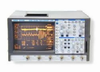
The 9314L is a 300 MHz, 4 Channel digital oscilloscope from LeCroy. Digital oscilloscopes make use of binary numbers that correspond to samples of the electronic equipment’s voltage. This is in contrast to analog oscilloscopes, which use continually varying voltages. Digital oscilloscopes use an analog-to-digital converter (ADC) to convert the voltages it measures into digital information.
Additional Features:
Simultaneous Maximum Sampling Rate/ch: 100 MSa/s
One ch. only max. sampling rate: 100 MSa/s
Max. Single Shot bandwidth: 300 MHz
Max. Record Length: 1000000 pt/sec
Vertical Sensitivity: 2 mV/div to 5 V/div
Number of Bits: 8 bits
Input Impedance: 1 M ω
Input Impedance (alternate): 50 ω
Input Coupling: AC,DC,GND
Maximum Input Voltage: 250 Vrms
Maximum Input#2 (for Impedance #2): 5 Vrms
Main time base: 1 ns/div-1000 s/div
Timebase accuracy: 0.002 %
Trigger Source: External,Internal
Trigger Modes: Auto, Drop, Logic, Normal, Single, Stop, Width
Minimum Trigger Holdoff: 25 ns
Trigger Sensitivity: 0.5 mV
Display Type: CRT Monochrome
Display Size: 22.86 cm
Display modes: Infinite, Normal, Persistence, X/Y
User Interface: Proprietary
Ports to Peripheral Devices: GPIB, RS232
Input Power: Universal (Auto Sense and Switch)
The LeCroy 9314L oscilloscope is a graph-displaying device – it draws a graph of an electrical signal. In most applications, the graph shows how signals change over time: the vertical (Y) axis represents voltage and the horizontal (X) axis represents time. The intensity or brightness of the display is sometimes called the Z axis.
The LeCroy 9314L oscilloscope's simple graph can tell you many things about a signal, such as: the time and voltage values of a signal, the frequency of an oscillating signal, the “moving parts” of a circuit represented by the signal, the frequency with which a particular portion of the signal is occurring relative to, other portions, whether or not a malfunctioning component is distorting the signal, how much of a signal is direct current (DC) or alternating current (AC) and how much of the signal is noise and whether the noise is changing with time.
The 9314L is a 300 MHz, 4 Channel digital oscilloscope from LeCroy. Digital oscilloscopes make use of binary numbers that correspond to samples of the electronic equipment’s voltage. This is in contrast to analog oscilloscopes, which use continually varying voltages. Digital oscilloscopes use an analog-to-digital converter (ADC) to convert the voltages it measures into digital information.
Additional Features:
- Simultaneous Maximum Sampling Rate/ch: 100 MSa/s
- One ch. only max. sampling rate: 100 MSa/s
- Max. Single Shot bandwidth: 300 MHz
- Max. Record Length: 1000000 pt/sec
- Vertical Sensitivity: 2 mV/div to 5 V/div
- Number of Bits: 8 bits
- Input Impedance: 1 M Ω
- Input Impedance (alternate): 50 Ω
- Input Coupling: AC,DC,GND
- Maximum Input Voltage: 250 Vrms
- Maximum Input#2 (for Impedance #2): 5 Vrms
- Main time base: 1 ns/div-1000 s/div
- Timebase accuracy: 0.002 %
- Trigger Source: External,Internal
- Trigger Modes: Auto, Drop, Logic, Normal, Single, Stop, Width
- Minimum Trigger Holdoff: 25 ns
- Trigger Sensitivity: 0.5 mV
- Display Type: CRT Monochrome
- Display Size: 22.86 cm
- Display modes: Infinite, Normal, Persistence, X/Y
- User Interface: Proprietary
- Ports to Peripheral Devices: GPIB, RS232
- Input Power: Universal (Auto Sense and Switch)
The LeCroy 9314L oscilloscope is a graph-displaying device – it draws a graph of an electrical signal. In most applications, the graph shows how signals change over time: the vertical (Y) axis represents voltage and the horizontal (X) axis represents time. The intensity or brightness of the display is sometimes called the Z axis.
The LeCroy 9314L oscilloscope's simple graph can tell you many things about a signal, such as: the time and voltage values of a signal, the frequency of an oscillating signal, the “moving parts” of a circuit represented by the signal, the frequency with which a particular portion of the signal is occurring relative to, other portions, whether or not a malfunctioning component is distorting the signal, how much of a signal is direct current (DC) or alternating current (AC) and how much of the signal is noise and whether the noise is changing with time.