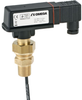
OMEGA Engineering, Inc. Flow Switch FSW300

Description
The FSW301 flow switch comprises a paddle system (1) with a permanent magnet attached (2). Above that magnet is a reed contact (3), located outside the flow of fluid. A second magnet with opposing poles (4) creates the force necessary to reset the switch back to the no flow position. When the monitored flow pushes the paddle and changes the position of the magnet (2) in relation to the reed contact (3) it activates the contact. As soon as the flow is interrupted, the paddle moves back to its starting position, which returns the reed contact to the initial position. The force necessary to push the magnet back is provided by the two magnets repelling each other. Using magnetic force instead of the usual leaf spring means the switch is considerably more stable in the long term and much less sensitive to pressure peaks. The reed contact used as a sensing element consists of two ferromagnetic contact blades located in a glass bulb filled with inert gas. This practically eliminates wear resulting from contact burning. This construction allows a useful life of up to 100,000,000 switching cycles.
Description
The FSW301 flow switch comprises a paddle system (1) with a permanent magnet attached (2). Above that magnet is a reed contact (3), located outside the flow of fluid. A second magnet with opposing poles (4) creates the force necessary to reset the switch back to the no flow position. When the monitored flow pushes the paddle and changes the position of the magnet (2) in relation to the reed contact (3) it activates the contact. As soon as the flow is interrupted, the paddle moves back to its starting position, which returns the reed contact to the initial position. The force necessary to push the magnet back is provided by the two magnets repelling each other. Using magnetic force instead of the usual leaf spring means the switch is considerably more stable in the long term and much less sensitive to pressure peaks. The reed contact used as a sensing element consists of two ferromagnetic contact blades located in a glass bulb filled with inert gas. This practically eliminates wear resulting from contact burning. This construction allows a useful life of up to 100,000,000 switching cycles.

Suppliers

Company
Product
Description
Supplier Links
Flow Switch - FSW300 - OMEGA Engineering, Inc.
Norwalk, CT, USA
Flow Switch
FSW300
Flow Switch FSW300
The FSW301 flow switch comprises a paddle system (1) with a permanent magnet attached (2). Above that magnet is a reed contact (3), located outside the flow of fluid. A second magnet with opposing poles (4) creates the force necessary to reset the switch back to the no flow position. When the monitored flow pushes the paddle and changes the position of the magnet (2) in relation to the reed contact (3) it activates the contact. As soon as the flow is interrupted, the paddle moves back to its starting position, which returns the reed contact to the initial position. The force necessary to push the magnet back is provided by the two magnets repelling each other. Using magnetic force instead of the usual leaf spring means the switch is considerably more stable in the long term and much less sensitive to pressure peaks. The reed contact used as a sensing element consists of two ferromagnetic contact blades located in a glass bulb filled with inert gas. This practically eliminates wear resulting from contact burning. This construction allows a useful life of up to 100,000,000 switching cycles.

The FSW301 flow switch comprises a paddle system (1) with a permanent magnet attached (2). Above that magnet is a reed contact (3), located outside the flow of fluid. A second magnet with opposing poles (4) creates the force necessary to reset the switch back to the no flow position.
When the monitored flow pushes the paddle and changes the position of the magnet (2) in relation to the reed contact (3) it activates the contact. As soon as the flow is interrupted, the paddle moves back to its starting position, which returns the reed contact to the initial position. The force necessary to push the magnet back is provided by the two magnets repelling each other. Using magnetic force instead of the usual leaf spring means the switch is considerably more stable in the long term and much less sensitive to pressure peaks.
The reed contact used as a sensing element consists of two ferromagnetic contact blades located in a glass bulb filled with inert gas. This practically eliminates wear resulting from contact burning. This construction allows a useful life of up to 100,000,000 switching cycles.

Buy Now

Technical Specifications

  OMEGA Engineering, Inc.
Product Category Volumetric Liquid Flow Switches
Product Number FSW300
Product Name Flow Switch
Meter Technology Paddlewheel
Meter Type Volumetric Flow Meter
Features Built-in Alarm Indicator
Pipe Diameter 0.50 to 8.00 inch (12.7 to 203 mm)
Mounting In-line
Unlock Full Specs
to access all available technical data
