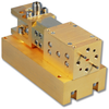

QuinStar Technology’s QMU series upconverters cover the frequency range of 18 to 110 GHz in seven waveguide bands. These upconverters have a balanced mixer configuration for high LO to RF isolation. They are constructed with a rugged, split-block mechanical design that utilizes GaAs beam-lead Schottky barrier diodes.
The upconverter combines LO and IF signals and produces RF output signals at frequencies of their sum and difference, i.e., LO ± IF. An optional integral waveguide filter is available to produce a single-sideband output signal. Typical IF bandwidth is a few GHz, but wider bandwidth upconverters are available. The LO and IF drive power levels determine the RF output power level. Typically, a high LO power level (near 17 dBm/50 mw) is needed to produce fully saturated RF output power of approximately 3 dBm. Conversion loss of the upconverter (defined as the difference between IF and RF output power) varies with LO drive level and IF input power. Generally, the RF output power varies linearly with IF signal below –10 dBm level, and hence conversion loss is nearly constant.
Local oscillator waveguide port may be in either the same waveguide band as RF waveguide port, or in a lower or higher waveguide band (the two adjacent bands), depending on LO frequency. The upconverter can supply several milliwatts of single-sideband output power with the proper input power levels. Upconverters are essential components in radars, communication systems and measurement instruments.
• Customized RF Bandwidth
• Low Conversion Loss
• High Output Power
• Integral Filter for SSB
| QuinStar Technology, Inc. | |
|---|---|
| Product Category | RF Frequency Converters |
| Product Number | QMU Series |
| Product Name | Upconverter |
| Converter Type | Upconverter |