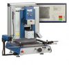

Featuring a (patented) aperture system to control and precisely apply the heat to protect adjacent components. The IR 3000 features a 500 W long wave top heater and a 1000 W long wave bottom heater. The standard PC software is the most advanced available on any rework system. Custom developed PID algorithms control the heating to your exacting specifications and make profiling easier than ever! Using a high quality, specially developed IR thermal sensor, the process is completely controlled using non contact measuring methods. For added verification, the SODR-CAM is available to watch the entire reflow process happen in real time.The process begins by loading your component into an adjustable nest which is then picked up using a vacuum pick. The part is lifted to the proper height above the optics and is now ready to be aligned to the PCB. Theta, X and Y adjustments are available to align the components. Precision micrometers are employed for adjusting the alignment in the X and Y directions. The system comes with four different size vacuum picks to handle a wide range of components. If flux dipping is needed, the part can be automatically dipped in flux prior to being aligned.The optical alignment system within the IR 3000 features a high resolution, color digital camera with PC controlled zoom, focus, auto-focus, and lighting control. The system is robust and does not require routine calibration or maintenance. Standard and full screen viewing options are available as part of the software. The optics extend and retract from the system automatically. High power ultra-white LED s are used to provide lighting to the component and PCB below while eliminating shadows and distortion. The vacuum pick can be set for each component so that when properly adjusted, the component is placed with almost zero force.Once the component is placed, the heating process begins. The system is unique in that it uses PACE Exclusive, custom developed, software based, PID controllers to control user determined ramp rates by selecting the time and the end temperature for each phase. Up to 3 additional data series plus the control sensor input can be stored with the profile or can be exported to a CSV file. The IR thermal sensor has a laser built in for easy alignment of the sensor to the part! The IR sensor is one of the most accurate available. If additional accuracy or verification is desired, a calibration method can be employed. As an option, a standard K type thermocouple input can be used in conjunction with a K-type thermocouple mounted to the PCB to control the process. If additional bottom side heat is needed for thermally massive or large PCBs, the bottom heater is adjustable up to 1.5".
| PACE | |
|---|---|
| Product Category | Welding, Brazing, and Soldering Equipment |
| Product Number | 8007-0534 |
| Product Name | IR 3000 |
| Equipment Type | IR 3000 |


PE, PP, PVDF