Oil-Rite Corp. Lubrication System Providing 2 GPM at 30 PSI, 30 Gal Tank, Air Cooled Heat Exchanger YC849-1

Description
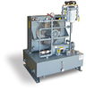
Oil-Rite manufactures Lubrication Systems specifically to customer requirements. All systems are engineered, designed, manufactured and fully tested at Oil-Rite. This is an example of a custom built Circulating Oil System. This Circulating Oil System is equipped with a cast iron pump providing 2 GPM at 30 PSI. The 1/2 HP, 1725 RPM, TEFC motor is operated by 3 phase power at 230/460V 60Hz. The 30 gallon capacity reservoir is constructed of welded steel. A top filler cap makes filling the reservoir quick and simple. The filler cap is equipped with an air filter and liquid strainer to help maintain liquid quality. There are (2) 1” female NPT returns and (2) 1/2” female NPT drains. A baffle in the tank separates sediment and reduces turbulence. A 100 mesh stainless steel suction filter inside the reservoir filters out larger debris. A low level switch inside the reservoir can be wired to shut down machinery or turn on warning devices when the liquid supply fails or recedes to a predetermined level. A conduit box and relay are provided for electrical connection of the low level switch. This system is plumbed for continuous operation with dual filtration systems. The (2) 23 micron, cellulose filters located near the outlet help maintain liquid quality. One filter can be serviced while maintaining continuous system operation using the duplicate filter. The filters feature spin-on elements for ease of cleaning and replacement. Dual differential pressure gages (one located across each filter) are provided to monitor circulation. An air cooled heat exchanger helps maintain a constant oil supply temperature. This system was designed for an application where oil circulates in at about 145° F and out at 135° F. The heat exchanger removes approximately 4,200 BTU/hr. The heat exchanger’s fan is powered by a 1/6 HP, 1140 RPM, TEFC motor operated by 3 phase power at 208-230/460V 60Hz. Additional controls include: A bronze check valve located at the system outlet ensures fluid flows in only one direction. A bypass relief valve used to set system pressure, adjustable from 7 to 35 PSI. A bypass relief valve located after the pump and used as a safety relief valve, set at 100 PSI. A dial thermometer displaying 0° to 250° F. A pressure switch located near the system outlet, adjustable from 0 to 60 PSI. A temperature switch located near the system outlet, adjustable from 75° to 205° F. A bronze flow switch located near the system outlet, adjustable from 1 to 6 GPM A stainless steel pressure gage displaying 0 - 60 PSI. A 5” centerline liquid level gage on the outside of the reservoir with a dial thermometer displaying temperatures from 0° to 250° F, allowing visual check of liquid level, condition, and temperature at a glance. A 5” centerline liquid level gage on the outside of the reservoir with a dial thermometer displaying temperatures from 0° to 250° F, allowing visual check of liquid level, condition, and temperature at a glance. This custom built circulating oil system measures 33” by 30”. The overall height is approximately 47 3/16”. The system can be secured using (4) mounting holes located on the base of the unit. All Circulating Oil Systems are quoted specifically to customer requirements. Pricing can be determined only after the Circulating Oil System Request Form ( found on this page) is completed. Contact the bearing manufacturer for information on the flow rate and fluid required. Delivery is dependent upon supplier availability, lead times range from 4 to 10 weeks.
Description
Oil-Rite manufactures Lubrication Systems specifically to customer requirements. All systems are engineered, designed, manufactured and fully tested at Oil-Rite. This is an example of a custom built Circulating Oil System. This Circulating Oil System is equipped with a cast iron pump providing 2 GPM at 30 PSI. The 1/2 HP, 1725 RPM, TEFC motor is operated by 3 phase power at 230/460V 60Hz. The 30 gallon capacity reservoir is constructed of welded steel. A top filler cap makes filling the reservoir quick and simple. The filler cap is equipped with an air filter and liquid strainer to help maintain liquid quality. There are (2) 1” female NPT returns and (2) 1/2” female NPT drains. A baffle in the tank separates sediment and reduces turbulence. A 100 mesh stainless steel suction filter inside the reservoir filters out larger debris. A low level switch inside the reservoir can be wired to shut down machinery or turn on warning devices when the liquid supply fails or recedes to a predetermined level. A conduit box and relay are provided for electrical connection of the low level switch. This system is plumbed for continuous operation with dual filtration systems. The (2) 23 micron, cellulose filters located near the outlet help maintain liquid quality. One filter can be serviced while maintaining continuous system operation using the duplicate filter. The filters feature spin-on elements for ease of cleaning and replacement. Dual differential pressure gages (one located across each filter) are provided to monitor circulation. An air cooled heat exchanger helps maintain a constant oil supply temperature. This system was designed for an application where oil circulates in at about 145° F and out at 135° F. The heat exchanger removes approximately 4,200 BTU/hr. The heat exchanger’s fan is powered by a 1/6 HP, 1140 RPM, TEFC motor operated by 3 phase power at 208-230/460V 60Hz. Additional controls include: A bronze check valve located at the system outlet ensures fluid flows in only one direction. A bypass relief valve used to set system pressure, adjustable from 7 to 35 PSI. A bypass relief valve located after the pump and used as a safety relief valve, set at 100 PSI. A dial thermometer displaying 0° to 250° F. A pressure switch located near the system outlet, adjustable from 0 to 60 PSI. A temperature switch located near the system outlet, adjustable from 75° to 205° F. A bronze flow switch located near the system outlet, adjustable from 1 to 6 GPM A stainless steel pressure gage displaying 0 - 60 PSI. A 5” centerline liquid level gage on the outside of the reservoir with a dial thermometer displaying temperatures from 0° to 250° F, allowing visual check of liquid level, condition, and temperature at a glance. A 5” centerline liquid level gage on the outside of the reservoir with a dial thermometer displaying temperatures from 0° to 250° F, allowing visual check of liquid level, condition, and temperature at a glance. This custom built circulating oil system measures 33” by 30”. The overall height is approximately 47 3/16”. The system can be secured using (4) mounting holes located on the base of the unit. All Circulating Oil Systems are quoted specifically to customer requirements. Pricing can be determined only after the Circulating Oil System Request Form ( found on this page) is completed. Contact the bearing manufacturer for information on the flow rate and fluid required. Delivery is dependent upon supplier availability, lead times range from 4 to 10 weeks.

Suppliers

Company
Product
Description
Supplier Links
Lubrication System Providing 2 GPM at 30 PSI, 30 Gal Tank, Air Cooled Heat Exchanger - YC849-1 - Oil-Rite Corp.
Manitowoc, WI, United States
Lubrication System Providing 2 GPM at 30 PSI, 30 Gal Tank, Air Cooled Heat Exchanger
YC849-1
Lubrication System Providing 2 GPM at 30 PSI, 30 Gal Tank, Air Cooled Heat Exchanger YC849-1
Oil-Rite manufactures Lubrication Systems specifically to customer requirements. All systems are engineered, designed, manufactured and fully tested at Oil-Rite. This is an example of a custom built Circulating Oil System. This Circulating Oil System is equipped with a cast iron pump providing 2 GPM at 30 PSI. The 1/2 HP, 1725 RPM, TEFC motor is operated by 3 phase power at 230/460V 60Hz. The 30 gallon capacity reservoir is constructed of welded steel. A top filler cap makes filling the reservoir quick and simple. The filler cap is equipped with an air filter and liquid strainer to help maintain liquid quality. There are (2) 1” female NPT returns and (2) 1/2” female NPT drains. A baffle in the tank separates sediment and reduces turbulence. A 100 mesh stainless steel suction filter inside the reservoir filters out larger debris. A low level switch inside the reservoir can be wired to shut down machinery or turn on warning devices when the liquid supply fails or recedes to a predetermined level. A conduit box and relay are provided for electrical connection of the low level switch. This system is plumbed for continuous operation with dual filtration systems. The (2) 23 micron, cellulose filters located near the outlet help maintain liquid quality. One filter can be serviced while maintaining continuous system operation using the duplicate filter. The filters feature spin-on elements for ease of cleaning and replacement. Dual differential pressure gages (one located across each filter) are provided to monitor circulation. An air cooled heat exchanger helps maintain a constant oil supply temperature. This system was designed for an application where oil circulates in at about 145° F and out at 135° F. The heat exchanger removes approximately 4,200 BTU/hr. The heat exchanger’s fan is powered by a 1/6 HP, 1140 RPM, TEFC motor operated by 3 phase power at 208-230/460V 60Hz. Additional controls include: A bronze check valve located at the system outlet ensures fluid flows in only one direction. A bypass relief valve used to set system pressure, adjustable from 7 to 35 PSI. A bypass relief valve located after the pump and used as a safety relief valve, set at 100 PSI. A dial thermometer displaying 0° to 250° F. A pressure switch located near the system outlet, adjustable from 0 to 60 PSI. A temperature switch located near the system outlet, adjustable from 75° to 205° F. A bronze flow switch located near the system outlet, adjustable from 1 to 6 GPM A stainless steel pressure gage displaying 0 - 60 PSI. A 5” centerline liquid level gage on the outside of the reservoir with a dial thermometer displaying temperatures from 0° to 250° F, allowing visual check of liquid level, condition, and temperature at a glance. A 5” centerline liquid level gage on the outside of the reservoir with a dial thermometer displaying temperatures from 0° to 250° F, allowing visual check of liquid level, condition, and temperature at a glance. This custom built circulating oil system measures 33” by 30”. The overall height is approximately 47 3/16”. The system can be secured using (4) mounting holes located on the base of the unit. All Circulating Oil Systems are quoted specifically to customer requirements. Pricing can be determined only after the Circulating Oil System Request Form ( found on this page) is completed. Contact the bearing manufacturer for information on the flow rate and fluid required. Delivery is dependent upon supplier availability, lead times range from 4 to 10 weeks.

Oil-Rite manufactures Lubrication Systems specifically to customer requirements. All systems are engineered, designed, manufactured and fully tested at Oil-Rite. This is an example of a custom built Circulating Oil System.

This Circulating Oil System is equipped with a cast iron pump providing 2 GPM at 30 PSI. The 1/2 HP, 1725 RPM, TEFC motor is operated by 3 phase power at 230/460V 60Hz.

The 30 gallon capacity reservoir is constructed of welded steel. A top filler cap makes filling the reservoir quick and simple. The filler cap is equipped with an air filter and liquid strainer to help maintain liquid quality. There are (2) 1” female NPT returns and (2) 1/2” female NPT drains. A baffle in the tank separates sediment and reduces turbulence. A 100 mesh stainless steel suction filter inside the reservoir filters out larger debris.

A low level switch inside the reservoir can be wired to shut down machinery or turn on warning devices when the liquid supply fails or recedes to a predetermined level. A conduit box and relay are provided for electrical connection of the low level switch.

This system is plumbed for continuous operation with dual filtration systems. The (2) 23 micron, cellulose filters located near the outlet help maintain liquid quality. One filter can be serviced while maintaining continuous system operation using the duplicate filter. The filters feature spin-on elements for ease of cleaning and replacement. Dual differential pressure gages (one located across each filter) are provided to monitor circulation.

An air cooled heat exchanger helps maintain a constant oil supply temperature. This system was designed for an application where oil circulates in at about 145° F and out at 135° F. The heat exchanger removes approximately 4,200 BTU/hr. The heat exchanger’s fan is powered by a 1/6 HP, 1140 RPM, TEFC motor operated by 3 phase power at 208-230/460V 60Hz.

Additional controls include:

  • A bronze check valve located at the system outlet ensures fluid flows in only one direction.
  • A bypass relief valve used to set system pressure, adjustable from 7 to 35 PSI.
  • A bypass relief valve located after the pump and used as a safety relief valve, set at 100 PSI.
  • A dial thermometer displaying 0° to 250° F.
  • A pressure switch located near the system outlet, adjustable from 0 to 60 PSI.
  • A temperature switch located near the system outlet, adjustable from 75° to 205° F.
  • A bronze flow switch located near the system outlet, adjustable from 1 to 6 GPM
  • A stainless steel pressure gage displaying 0 - 60 PSI.
  • A 5” centerline liquid level gage on the outside of the reservoir with a dial thermometer displaying temperatures from 0° to 250° F, allowing visual check of liquid level, condition, and temperature at a glance.

A 5” centerline liquid level gage on the outside of the reservoir with a dial thermometer displaying temperatures from 0° to 250° F, allowing visual check of liquid level, condition, and temperature at a glance.

This custom built circulating oil system measures 33” by 30”. The overall height is approximately 47 3/16”. The system can be secured using (4) mounting holes located on the base of the unit.

All Circulating Oil Systems are quoted specifically to customer requirements. Pricing can be determined only after the Circulating Oil System Request Form ( found on this page) is completed. Contact the bearing manufacturer for information on the flow rate and fluid required.

Delivery is dependent upon supplier availability, lead times range from 4 to 10 weeks.

Supplier's Site

Technical Specifications

  Oil-Rite Corp.
Product Category Lubricators and Lubrication Systems
Product Number YC849-1
Product Name Lubrication System Providing 2 GPM at 30 PSI, 30 Gal Tank, Air Cooled Heat Exchanger
Feed Type Circulating Oil
Unlock Full Specs
to access all available technical data

Similar Products

Pneumatic Lubricators - 1761744 - RS Components, Ltd.
Specs
Operating Pressure 218 psi (153 m H2O)
View Details
Pulsed Lubrication System, MicroCoat® MC781S Series -  - Nordson EFD
Specs
Delivery Constant Level; Pulsed
Feed Type Multi-line
Feed Style Progressive
View Details
Automatic Lubrication System - Flexxpump - Andantex USA, Inc.
Specs
Feed Type Multi-line
Application Chain; Rack and Pinions, Open Gearing, Linear Guideways, Ballscrews
Operating Temperature -13 to 158 F (-25 to 70 C)
View Details
Oil Cups -  - G.L. Huyett
G.L. Huyett
Specs
Delivery Constant Level
Feed Type Single Line
Application General Purpose
View Details