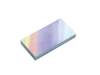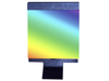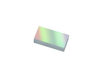

The 33066FL01-080R Plane Ruled Reflection Grating is 12.5 x 25 mm and 6 mm thick. The grating has 600 grooves per mm a nominal wavelength at 400 nm, and a nominal blaze angle of 7.0°. The diffraction grating is coated with an aluminum coating on float glass substrate and designed for first order Littrow use with high efficiency in the spectral region around the blaze wavelength.
Plane Ruled Diffraction Grating Construction
In general, for ruled diffraction gratings the groove spacing determines the diffraction angles, and the groove depth and blaze angle determines how diffracted energy is distributed between diffraction orders. Designed for first order Littrow use, Newport’s Plane Ruled Reflection Gratings are blazed to achieve extremely high single-order diffraction efficiency at particular design wavelengths. At Newport, we have three ruling engines in full-time operation, each producing high-quality master gratings each year. These ruling engines provide gratings with triangular groove profiles, very low Rowland ghosts, and high resolving power. Mechanically ruled, individual grooves are burnished with a diamond tool against a thin coating of evaporated metal. Utilizing a high fidelity cast replication process, developed and enhanced through years of research and manufacturing experience, we have the ability to provide duplicates of master gratings that equal the quality and performance of the master grating.
Optimum Diffraction Grating Orientation
Plane Ruled Diffraction Gratings are most efficient when used near the design wavelength in the Littrow configuration, that is aligned so that the diffraction angle of the dominant diffraction order is coincident with the input beam, effectively behaving as a retroreflector at a specific wavelength. For blazed gratings, maximum efficiency occurs for wavelengths that the Littrow condition at the angle normal to the blazed grating facets. As ruled blaze gratings are asymmetric, correct orientation is indicated with an arrow marking on the size of the substrate. The arrow is on the side of the substrate perpendicular to the ruled grooves, and points toward the steeper edge of the triangular groove profile. Equivalently, the arrow points away from the grating normal toward the facet normal. The arrow should point toward the incident (and diffracted) beam.
The Grating Equation
The basic grating equation determines the discrete directions into which monochromatic light of wavelength λ is diffracted. The equation is shown below:
mλ = dG (sinα + sinβm)
The above figure illustrates this diffraction. Light of wavelength λ is incident at an angle α and diffracted by the grating (with a groove spacing dG) along a set of angles βm. These angles are measured from the grating normal, which is shown as the dashed line perpendicular to the grating surface at its center. If βm is on the opposite side of the grating normal from α, its sign is opposite. In the equation, m is the order of diffraction, which is an integer. For the zeroth order (m = 0), α and β0 are equal and opposite, resulting in the light simply being reflected, i.e., no diffraction. The sign convention for m requires that it is positive if the diffracted ray lies to the left (counter-clockwise side) of the zeroth order and negative if it lies to the right (the clockwise side). When a beam of monochromatic light is incident on a grating, the light is simply diffracted from the grating in directions corresponding to m = -2, -1, 0, 1, 2, 3, etc. When a beam of polychromatic light is incident on a grating, then the light is dispersed so that each wavelength satisfies the grating equation as shown in the figure. Usually only the first order, positive or negative, is desired and so higher order wavelengths may need to be blocked. In many monochromators and spectrographs, a constant-deviation mount is used where the wavelength is changed by rotating the grating around an axis while the angle between the incident and diffracted light (or deviation angle) remains unchanged.
| Newport MKS | |
|---|---|
| Product Category | Diffraction Gratings |
| Product Number | 33066FL01-080R |
| Product Name | Ruled Diffraction Grating, 12.5 x 25 mm, 400 nm, 7.0° Blaze, 600 g/mm |
| Grating Type | Ruled |
| Grating Design | Plane Reflection |
| Groove Frequency | 600 grooves per mm (15240 grooves per inch) |