Microchip Technology, Inc. High Voltage EL Lamp Driver HV833

Description
HV833 is a high voltage driver designed for driving EL lamps of up to 35nF (10-12in2). The input supply voltage range is from 1.8 to 6.5V. The device uses a single inductor and a minimum number of passive components. The nominal regulated output voltage that is applied to the EL lamp is ±90V. The chip can be enabled/disabled by connecting a resistor between the RSW-Osc pin and the VDD/GND pins. The HV833 has two internal oscillators, a switching MOSFET, and a high voltage EL lamp driver. The frequency for the switching MOSFET is set by an external resistor connected between the RSW-Osc pin and the VDD supply pin. The EL lamp driver frequency is set by an external resistor connected between the REL-Osc pin and the VDD pin. An external inductor is connected between the LX pin and VDD or VIN pin. A 0.003-0.1µF capacitor is connected between the CS pin and the GND pin. The EL lamp is connected between the VA pin and the VB pin. The switching MOSFET charges the external inductor and discharges it into the capacitor at CS. The voltage at CS will start to increase. Once the voltage at CS reaches a nominal value of 90V, the switching MOSFET is turned OFF to conserve power. The outputs VA and VB are configured as an H bridge and are switching in opposite states to achieve 180V peak-to-peak across the EL lamp. Additional Features 1.8 to 6.5V operating supply voltage DC to AC conversion Separately adjustable lamp and converter frequency Output voltage regulation Enable/disable function Patented output timing for high efficiency <100nA shutdown current Split supply capability LCD backlighting
Datasheet
Description
HV833 is a high voltage driver designed for driving EL lamps of up to 35nF (10-12in2). The input supply voltage range is from 1.8 to 6.5V. The device uses a single inductor and a minimum number of passive components. The nominal regulated output voltage that is applied to the EL lamp is ±90V. The chip can be enabled/disabled by connecting a resistor between the RSW-Osc pin and the VDD/GND pins. The HV833 has two internal oscillators, a switching MOSFET, and a high voltage EL lamp driver. The frequency for the switching MOSFET is set by an external resistor connected between the RSW-Osc pin and the VDD supply pin. The EL lamp driver frequency is set by an external resistor connected between the REL-Osc pin and the VDD pin. An external inductor is connected between the LX pin and VDD or VIN pin. A 0.003-0.1µF capacitor is connected between the CS pin and the GND pin. The EL lamp is connected between the VA pin and the VB pin. The switching MOSFET charges the external inductor and discharges it into the capacitor at CS. The voltage at CS will start to increase. Once the voltage at CS reaches a nominal value of 90V, the switching MOSFET is turned OFF to conserve power. The outputs VA and VB are configured as an H bridge and are switching in opposite states to achieve 180V peak-to-peak across the EL lamp. Additional Features 1.8 to 6.5V operating supply voltage DC to AC conversion Separately adjustable lamp and converter frequency Output voltage regulation Enable/disable function Patented output timing for high efficiency <100nA shutdown current Split supply capability LCD backlighting
Datasheet

Suppliers

Company
Product
Description
Supplier Links
High Voltage EL Lamp Driver - HV833 - Microchip Technology, Inc.
Chandler, AZ, United States
High Voltage EL Lamp Driver
HV833
High Voltage EL Lamp Driver HV833
HV833 is a high voltage driver designed for driving EL lamps of up to 35nF (10-12in2). The input supply voltage range is from 1.8 to 6.5V. The device uses a single inductor and a minimum number of passive components. The nominal regulated output voltage that is applied to the EL lamp is ±90V. The chip can be enabled/disabled by connecting a resistor between the RSW-Osc pin and the VDD/GND pins. The HV833 has two internal oscillators, a switching MOSFET, and a high voltage EL lamp driver. The frequency for the switching MOSFET is set by an external resistor connected between the RSW-Osc pin and the VDD supply pin. The EL lamp driver frequency is set by an external resistor connected between the REL-Osc pin and the VDD pin. An external inductor is connected between the LX pin and VDD or VIN pin. A 0.003-0.1µF capacitor is connected between the CS pin and the GND pin. The EL lamp is connected between the VA pin and the VB pin. The switching MOSFET charges the external inductor and discharges it into the capacitor at CS. The voltage at CS will start to increase. Once the voltage at CS reaches a nominal value of 90V, the switching MOSFET is turned OFF to conserve power. The outputs VA and VB are configured as an H bridge and are switching in opposite states to achieve 180V peak-to-peak across the EL lamp. Additional Features 1.8 to 6.5V operating supply voltage DC to AC conversion Separately adjustable lamp and converter frequency Output voltage regulation Enable/disable function Patented output timing for high efficiency <100nA shutdown current Split supply capability LCD backlighting

HV833 is a high voltage driver designed for driving EL lamps of up to 35nF (10-12in2). The input supply voltage range is from 1.8 to 6.5V. The device uses a single inductor and a minimum number of passive components. The nominal regulated output voltage that is applied to the EL lamp is ±90V. The chip can be enabled/disabled by connecting a resistor between the RSW-Osc pin and the VDD/GND pins. The HV833 has two internal oscillators, a switching MOSFET, and a high voltage EL lamp driver. The frequency for the switching MOSFET is set by an external resistor connected between the RSW-Osc pin and the VDD supply pin. The EL lamp driver frequency is set by an external resistor connected between the REL-Osc pin and the VDD pin. An external inductor is connected between the LX pin and VDD or VIN pin. A 0.003-0.1µF capacitor is connected between the CS pin and the GND pin. The EL lamp is connected between the VA pin and the VB pin. The switching MOSFET charges the external inductor and discharges it into the capacitor at CS. The voltage at CS will start to increase. Once the voltage at CS reaches a nominal value of 90V, the switching MOSFET is turned OFF to conserve power. The outputs VA and VB are configured as an H bridge and are switching in opposite states to achieve 180V peak-to-peak across the EL lamp.

Additional Features

  • 1.8 to 6.5V operating supply voltage
  • DC to AC conversion
  • Separately adjustable lamp and converter frequency
  • Output voltage regulation
  • Enable/disable function
  • Patented output timing for high efficiency
  • <100nA shutdown current
  • Split supply capability
  • LCD backlighting
Supplier's Site Datasheet

Technical Specifications

  Microchip Technology, Inc.
Product Category Gate Drivers
Product Number HV833
Product Name High Voltage EL Lamp Driver
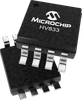
Package Type MSOP-8
Unlock Full Specs
to access all available technical data

Similar Products

Clock Buffers, Drivers - 54AC2525WFQMLV - Quarktwin Technology Ltd.
Specs
Output Configuration Inverting
Supply Voltage 2 to 6 volts
Operating Temperature -55 to 125 C (-67 to 257 F)
View Details
LED Drivers - AAT2823IBK-T1 - Quarktwin Technology Ltd.
Skyworks Solutions, Inc.
Specs
Number of Outputs 1; 1
Output Configuration Inverting; Step-Up (Boost)
Output Voltage 14.5 volts
View Details
Full Half-Bridge Drivers - 111-4126PBF - Quarktwin Technology Ltd.
Specs
Output Configuration Inverting
Packing Method Tube; Tube; Other
View Details