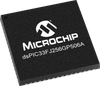
•dsPIC33Fs are designed to execute digital filter algorithms and high-speed precision digital control loops, ideal for applications that need to perform under pressure •General Purpose Digital Signal Controllers (DSCs) with advanced analog and seamless migration options to PIC24F, PIC24H MCUs and dsPIC30F DSCs
Additional Features
Operating Conditions
Up to 40 MIPS operation
3.0V to 3.6V, -40ºC to +150ºC, DC to 20 MIPS
3.0V to 3.6V, -40ºC to +125ºC, DC to 40 MIPS
High-performance dsPIC33F core
Code-efficient (C and Assembly) architecture
Two 40-bit wide accumulators
Single-cycle (MAC/MPY) with dual data fetch
Single-cycle mixed-sign MUL plus hardware divide
Clock Management
Programmable PLLs and oscillator clock sources
±2% internal oscillator
Fail-Safe Clock Monitor (FSCM)
Independent Watchdog Timer (WDT)
Fast wake-up and start-up
Power Management
Low-power management modes (Sleep, Idle, Doze)
Integrated Power-on Reset and Brown-out Reset
2.1 mA/MHz dynamic current (typical)
50 μA IPD current (typical)
Advanced Analog Features
Two ADC modules: - Configurable as 10-bit, 1.1 Msps with four S&H or 12-bit, 500 ksps with one S&H - 18 analog inputs on 64-pin devices and up to 32 analog inputs on 100-pin devices
Flexible and independent ADC trigger sources
Timers/Output Compare/Input Capture
Up to nine 16-bit timers/counters (Can pair up to make four 32-bit timers)
Eight Output Compare modules configurable as timers/counters
Eight Input Capture modules Communication Interfaces
Two UART modules (10 Mbps) - With support for LIN 2.0 protocols and IrDA®
Two 4-wire SPI modules (15 Mbps)
Up to two I2C™ modules (up to 1 Mbaud) with SM Bus support
Enhanced CAN (ECAN) module (1 Mbaud) with CAN 2.0B support
Data Converter Interface (DCI) module with I2S codec support
Input/Output
Sink/Source up to 10 mA (pin specific) for standard VOH/VOL, up to 16 mA (pin specific) for non-standard VOH1
5V-tolerant pins
Selectable open drain, pull-ups, and pull-downs
Up to 5 mA overvoltage clamp current
External interrupts on all I/O pins
Debugger Development Support
In-circuit and in-application programming
Two program and two complex data breakpoints
IEEE 1149.2-compatible (JTAG) boundary scan
Trace and run-time watch
•dsPIC33Fs are designed to execute digital filter algorithms and high-speed precision digital control loops, ideal for applications that need to perform under pressure •General Purpose Digital Signal Controllers (DSCs) with advanced analog and seamless migration options to PIC24F, PIC24H MCUs and dsPIC30F DSCs
Additional Features
- Operating Conditions
- Up to 40 MIPS operation
- 3.0V to 3.6V, -40ºC to +150ºC, DC to 20 MIPS
- 3.0V to 3.6V, -40ºC to +125ºC, DC to 40 MIPS
- High-performance dsPIC33F core
- Code-efficient (C and Assembly) architecture
- Two 40-bit wide accumulators
- Single-cycle (MAC/MPY) with dual data fetch
- Single-cycle mixed-sign MUL plus hardware divide
- Clock Management
- Programmable PLLs and oscillator clock sources
- ±2% internal oscillator
- Fail-Safe Clock Monitor (FSCM)
- Independent Watchdog Timer (WDT)
- Fast wake-up and start-up
- Power Management
- Low-power management modes (Sleep, Idle, Doze)
- Integrated Power-on Reset and Brown-out Reset
- 2.1 mA/MHz dynamic current (typical)
- 50 μA IPD current (typical)
- Advanced Analog Features
- Two ADC modules: - Configurable as 10-bit, 1.1 Msps with four S&H or 12-bit, 500 ksps with one S&H - 18 analog inputs on 64-pin devices and up to 32 analog inputs on 100-pin devices
- Flexible and independent ADC trigger sources
- Timers/Output Compare/Input Capture
- Up to nine 16-bit timers/counters (Can pair up to make four 32-bit timers)
- Eight Output Compare modules configurable as timers/counters
- Eight Input Capture modules Communication Interfaces
- Two UART modules (10 Mbps) - With support for LIN 2.0 protocols and IrDA®
- Two 4-wire SPI modules (15 Mbps)
- Up to two I2C™ modules (up to 1 Mbaud) with SM Bus support
- Enhanced CAN (ECAN) module (1 Mbaud) with CAN 2.0B support
- Data Converter Interface (DCI) module with I2S codec support
- Input/Output
- Sink/Source up to 10 mA (pin specific) for standard VOH/VOL, up to 16 mA (pin specific) for non-standard VOH1
- 5V-tolerant pins
- Selectable open drain, pull-ups, and pull-downs
- Up to 5 mA overvoltage clamp current
- External interrupts on all I/O pins
- Debugger Development Support
- In-circuit and in-application programming
- Two program and two complex data breakpoints
- IEEE 1149.2-compatible (JTAG) boundary scan
- Trace and run-time watch