Microchip Technology, Inc. ATSAMG55J19B

Description
The Microchip's SAM G55 embeds a Cortex-M4 CPU with an FPU (floating point unit). This ensures maximum throughput. This is very important as it allows you to minimize the active power consumption and get to sleep faster in order to reduce the overall power consumption. Additionally, the devices have 30 DMA channels, which give extremely high throughput. The combination of ultra-low power consumption, fast wake-up time and high throughput is what gives the SAM G the edge in space- and power-constrained consumer applications such as sensor hubs. It wakes up quickly, has the throughput needed to reduce the amount of time spent in active mode, and then goes back to sleep with SRAM retention to conserve energy. This gives the best performance and longest battery lifetime. It is fully-functional all the way down to 1.6V; including flash reads and writes, as well as full ADC operation. This allows for a more flexible power supply scheme that will squeeze extra runtime out of a battery. Supported by MPLAB X IDE and MPLAB Harmony. Additional Features Key Features picoPower Down to 100 µA/MHz in active Below 7 µA in deep sleep with SRAM retention Down to 3 µs wake-up from deep sleep to executing the first instruction in active mode Increased throughput Cortex-M4 FPU Small package 3x3 mm w/ 0.4mm pitch, WLCSP 7x7 pins Pin compatibility across the family Microcontroller Features Core ARM Cortex-M4 with up to 16 Kbytes SRAM on I/D bus providing 0 wait state execution at up to 120 MHz Memory Protection Unit (MPU) DSP Instructions, Floating Point Unit (FPU), Thumb®-2 instruction set Memories Up to 512 Kbytes embedded Flash Up to 176 Kbytes embedded SRAM 8 Kbytes ROM with embedded boot loader, single-cycle access at full speed System Embedded voltage regulator for single-supply operation Power-on reset (POR) and Watchdog for safe operation Quartz or ceramic resonator oscillators: 3 to 20 MHz with clock failure detection and 32.768 kHz for RTT or system clock High-precision 8/16/24 MHz factory-trimmed internal RC oscillator. In-application trimming access for frequency adjustment Slow clock internal RC oscillator as permanent low-power mode device clock PLL range from 48 MHz to 120 MHz for device clock PLL range from 24 MHz to 48 MHz for USB device and USB OHCI Up to 30 peripheral DMA (PDC) channels 256-bit General-Purpose Backup Registers (GPBR) 16 external interrupt lines Package 49-lead WLCSP, 64-lead LQFP, 64-lead QFN Temperature operating range Industrial (-40° C to +85° C) Peripheral Features 8 flexible communication units supporting: USART, SPI, or Two-wire Interface (TWI) USB 2.0 Device and USB Host OHCI with On-chip Transceiver 2 Inter-IC Sound Controllers (I2S) 2 three-channel 16-bit Timer/Counters (TC) with capture, waveform, compare and PWM modes 1 48-bit Real-Time Timer (RTT) with 16-bit prescaler and 32-bit counter 1 RTC with calendar and alarm features 1 32-bit Cyclic Redundancy Check Calculation Unit (CRCCU) I/O Up to 48 I/O lines with external interrupt capability (edge or level), debouncing, glitch filtering and on-die series resistor termination. Individually programmable open-drain, pull-up and pull-down resistor and synchronous output Two PIO Controllers provide control of up to 48 I/O lines Audio Features 1 Pulse Density Modulation Interface (PDMIC) (supports up to two microphones) Advanced Analog Features 12-bit ADC Module: One 8-channel ADC, 500 kSps Conversion Rate 12-bit Resolution with Enhanced Mode up to 16 bits Digital Averaging Function providing Enhanced Resolution Mode up to 16 bits Integrated Multiplexer Offering Up to 8 Independent Analog Inputs Standby Mode for Fast Wakeup Time Response Asynchronous Partial Wake-up (Sleepwalking) on external trigger Debugger Development Support Serial Wire/JTAG Debug Port(SWJ-DP) Debug access to all memories and registers in the system, including Cortex-M4 register bank when the core is running, halted, or held in reset. Serial Wire Debug Port (SW-DP) and Serial Wire JTAG Debug Port (SWJ-DP) debug access. Flash Patch and Breakpoint (FPB) unit for implementing breakpoints and code patches. Data Watchpoint and Trace (DWT) unit for implementing watchpoints, data tracing, and system profiling. Instrumentation Trace Macrocell (ITM) for support of printf style debugging. IEEE1149.1 JTAG Boundary-scan on all digital pins. Integrated Software Libraries and Tools ASF-Atmel software Framework – SAM software development framework Integrated in the Atmel Studio IDE with a graphical user interface or available as standalone for GCC, IAR compilers. DMA support, Interrupt handlers Driver support USB, TCP/IP, Wi-Fi and Bluetooth, Numerous USB classes, DHCP and Wi-Fi encryption Stacks Image formats, file system & GUI library Middleware RTOS integration, FreeRTOS a core component
Datasheet
Description
The Microchip's SAM G55 embeds a Cortex-M4 CPU with an FPU (floating point unit). This ensures maximum throughput. This is very important as it allows you to minimize the active power consumption and get to sleep faster in order to reduce the overall power consumption. Additionally, the devices have 30 DMA channels, which give extremely high throughput. The combination of ultra-low power consumption, fast wake-up time and high throughput is what gives the SAM G the edge in space- and power-constrained consumer applications such as sensor hubs. It wakes up quickly, has the throughput needed to reduce the amount of time spent in active mode, and then goes back to sleep with SRAM retention to conserve energy. This gives the best performance and longest battery lifetime. It is fully-functional all the way down to 1.6V; including flash reads and writes, as well as full ADC operation. This allows for a more flexible power supply scheme that will squeeze extra runtime out of a battery. Supported by MPLAB X IDE and MPLAB Harmony. Additional Features Key Features picoPower Down to 100 µA/MHz in active Below 7 µA in deep sleep with SRAM retention Down to 3 µs wake-up from deep sleep to executing the first instruction in active mode Increased throughput Cortex-M4 FPU Small package 3x3 mm w/ 0.4mm pitch, WLCSP 7x7 pins Pin compatibility across the family Microcontroller Features Core ARM Cortex-M4 with up to 16 Kbytes SRAM on I/D bus providing 0 wait state execution at up to 120 MHz Memory Protection Unit (MPU) DSP Instructions, Floating Point Unit (FPU), Thumb®-2 instruction set Memories Up to 512 Kbytes embedded Flash Up to 176 Kbytes embedded SRAM 8 Kbytes ROM with embedded boot loader, single-cycle access at full speed System Embedded voltage regulator for single-supply operation Power-on reset (POR) and Watchdog for safe operation Quartz or ceramic resonator oscillators: 3 to 20 MHz with clock failure detection and 32.768 kHz for RTT or system clock High-precision 8/16/24 MHz factory-trimmed internal RC oscillator. In-application trimming access for frequency adjustment Slow clock internal RC oscillator as permanent low-power mode device clock PLL range from 48 MHz to 120 MHz for device clock PLL range from 24 MHz to 48 MHz for USB device and USB OHCI Up to 30 peripheral DMA (PDC) channels 256-bit General-Purpose Backup Registers (GPBR) 16 external interrupt lines Package 49-lead WLCSP, 64-lead LQFP, 64-lead QFN Temperature operating range Industrial (-40° C to +85° C) Peripheral Features 8 flexible communication units supporting: USART, SPI, or Two-wire Interface (TWI) USB 2.0 Device and USB Host OHCI with On-chip Transceiver 2 Inter-IC Sound Controllers (I2S) 2 three-channel 16-bit Timer/Counters (TC) with capture, waveform, compare and PWM modes 1 48-bit Real-Time Timer (RTT) with 16-bit prescaler and 32-bit counter 1 RTC with calendar and alarm features 1 32-bit Cyclic Redundancy Check Calculation Unit (CRCCU) I/O Up to 48 I/O lines with external interrupt capability (edge or level), debouncing, glitch filtering and on-die series resistor termination. Individually programmable open-drain, pull-up and pull-down resistor and synchronous output Two PIO Controllers provide control of up to 48 I/O lines Audio Features 1 Pulse Density Modulation Interface (PDMIC) (supports up to two microphones) Advanced Analog Features 12-bit ADC Module: One 8-channel ADC, 500 kSps Conversion Rate 12-bit Resolution with Enhanced Mode up to 16 bits Digital Averaging Function providing Enhanced Resolution Mode up to 16 bits Integrated Multiplexer Offering Up to 8 Independent Analog Inputs Standby Mode for Fast Wakeup Time Response Asynchronous Partial Wake-up (Sleepwalking) on external trigger Debugger Development Support Serial Wire/JTAG Debug Port(SWJ-DP) Debug access to all memories and registers in the system, including Cortex-M4 register bank when the core is running, halted, or held in reset. Serial Wire Debug Port (SW-DP) and Serial Wire JTAG Debug Port (SWJ-DP) debug access. Flash Patch and Breakpoint (FPB) unit for implementing breakpoints and code patches. Data Watchpoint and Trace (DWT) unit for implementing watchpoints, data tracing, and system profiling. Instrumentation Trace Macrocell (ITM) for support of printf style debugging. IEEE1149.1 JTAG Boundary-scan on all digital pins. Integrated Software Libraries and Tools ASF-Atmel software Framework – SAM software development framework Integrated in the Atmel Studio IDE with a graphical user interface or available as standalone for GCC, IAR compilers. DMA support, Interrupt handlers Driver support USB, TCP/IP, Wi-Fi and Bluetooth, Numerous USB classes, DHCP and Wi-Fi encryption Stacks Image formats, file system & GUI library Middleware RTOS integration, FreeRTOS a core component
Datasheet

Suppliers

Company
Product
Description
Supplier Links
The Microchip's SAM G55 embeds a Cortex-M4 CPU with an FPU (floating point unit). This ensures maximum throughput. This is very important as it allows you to minimize the active power consumption and get to sleep faster in order to reduce the overall power consumption. Additionally, the devices have 30 DMA channels, which give extremely high throughput. The combination of ultra-low power consumption, fast wake-up time and high throughput is what gives the SAM G the edge in space- and power-constrained consumer applications such as sensor hubs. It wakes up quickly, has the throughput needed to reduce the amount of time spent in active mode, and then goes back to sleep with SRAM retention to conserve energy. This gives the best performance and longest battery lifetime. It is fully-functional all the way down to 1.6V; including flash reads and writes, as well as full ADC operation. This allows for a more flexible power supply scheme that will squeeze extra runtime out of a battery. Supported by MPLAB X IDE and MPLAB Harmony. Additional Features Key Features picoPower Down to 100 µA/MHz in active Below 7 µA in deep sleep with SRAM retention Down to 3 µs wake-up from deep sleep to executing the first instruction in active mode Increased throughput Cortex-M4 FPU Small package 3x3 mm w/ 0.4mm pitch, WLCSP 7x7 pins Pin compatibility across the family Microcontroller Features Core ARM Cortex-M4 with up to 16 Kbytes SRAM on I/D bus providing 0 wait state execution at up to 120 MHz Memory Protection Unit (MPU) DSP Instructions, Floating Point Unit (FPU), Thumb®-2 instruction set Memories Up to 512 Kbytes embedded Flash Up to 176 Kbytes embedded SRAM 8 Kbytes ROM with embedded boot loader, single-cycle access at full speed System Embedded voltage regulator for single-supply operation Power-on reset (POR) and Watchdog for safe operation Quartz or ceramic resonator oscillators: 3 to 20 MHz with clock failure detection and 32.768 kHz for RTT or system clock High-precision 8/16/24 MHz factory-trimmed internal RC oscillator. In-application trimming access for frequency adjustment Slow clock internal RC oscillator as permanent low-power mode device clock PLL range from 48 MHz to 120 MHz for device clock PLL range from 24 MHz to 48 MHz for USB device and USB OHCI Up to 30 peripheral DMA (PDC) channels 256-bit General-Purpose Backup Registers (GPBR) 16 external interrupt lines Package 49-lead WLCSP, 64-lead LQFP, 64-lead QFN Temperature operating range Industrial (-40° C to +85° C) Peripheral Features 8 flexible communication units supporting: USART, SPI, or Two-wire Interface (TWI) USB 2.0 Device and USB Host OHCI with On-chip Transceiver 2 Inter-IC Sound Controllers (I2S) 2 three-channel 16-bit Timer/Counters (TC) with capture, waveform, compare and PWM modes 1 48-bit Real-Time Timer (RTT) with 16-bit prescaler and 32-bit counter 1 RTC with calendar and alarm features 1 32-bit Cyclic Redundancy Check Calculation Unit (CRCCU) I/O Up to 48 I/O lines with external interrupt capability (edge or level), debouncing, glitch filtering and on-die series resistor termination. Individually programmable open-drain, pull-up and pull-down resistor and synchronous output Two PIO Controllers provide control of up to 48 I/O lines Audio Features 1 Pulse Density Modulation Interface (PDMIC) (supports up to two microphones) Advanced Analog Features 12-bit ADC Module: One 8-channel ADC, 500 kSps Conversion Rate 12-bit Resolution with Enhanced Mode up to 16 bits Digital Averaging Function providing Enhanced Resolution Mode up to 16 bits Integrated Multiplexer Offering Up to 8 Independent Analog Inputs Standby Mode for Fast Wakeup Time Response Asynchronous Partial Wake-up (Sleepwalking) on external trigger Debugger Development Support Serial Wire/JTAG Debug Port(SWJ-DP) Debug access to all memories and registers in the system, including Cortex-M4 register bank when the core is running, halted, or held in reset. Serial Wire Debug Port (SW-DP) and Serial Wire JTAG Debug Port (SWJ-DP) debug access. Flash Patch and Breakpoint (FPB) unit for implementing breakpoints and code patches. Data Watchpoint and Trace (DWT) unit for implementing watchpoints, data tracing, and system profiling. Instrumentation Trace Macrocell (ITM) for support of printf style debugging. IEEE1149.1 JTAG Boundary-scan on all digital pins. Integrated Software Libraries and Tools ASF-Atmel software Framework – SAM software development framework Integrated in the Atmel Studio IDE with a graphical user interface or available as standalone for GCC, IAR compilers. DMA support, Interrupt handlers Driver support USB, TCP/IP, Wi-Fi and Bluetooth, Numerous USB classes, DHCP and Wi-Fi encryption Stacks Image formats, file system & GUI library Middleware RTOS integration, FreeRTOS a core component

The Microchip's SAM G55 embeds a Cortex-M4 CPU with an FPU (floating point unit). This ensures maximum throughput. This is very important as it allows you to minimize the active power consumption and get to sleep faster in order to reduce the overall power consumption. Additionally, the devices have 30 DMA channels, which give extremely high throughput.

The combination of ultra-low power consumption, fast wake-up time and high throughput is what gives the SAM G the edge in space- and power-constrained consumer applications such as sensor hubs. It wakes up quickly, has the throughput needed to reduce the amount of time spent in active mode, and then goes back to sleep with SRAM retention to conserve energy.

This gives the best performance and longest battery lifetime. It is fully-functional all the way down to 1.6V; including flash reads and writes, as well as full ADC operation. This allows for a more flexible power supply scheme that will squeeze extra runtime out of a battery.


Supported by MPLAB X IDE and MPLAB Harmony. Additional Features

  • Key Features
    • picoPower
    • Down to 100 µA/MHz in active
    • Below 7 µA in deep sleep with SRAM retention
    • Down to 3 µs wake-up from deep sleep to executing the first instruction in active mode
    • Increased throughput
    • Cortex-M4
    • FPU
    • Small package
    • 3x3 mm w/ 0.4mm pitch, WLCSP 7x7 pins
    • Pin compatibility across the family
  • Microcontroller Features
  • Core
    • ARM Cortex-M4 with up to 16 Kbytes SRAM on I/D bus providing 0 wait state execution at up to 120 MHz
    • Memory Protection Unit (MPU)
    • DSP Instructions, Floating Point Unit (FPU), Thumb®-2 instruction set
  • Memories
    • Up to 512 Kbytes embedded Flash
    • Up to 176 Kbytes embedded SRAM
    • 8 Kbytes ROM with embedded boot loader, single-cycle access at full speed
  • System
    • Embedded voltage regulator for single-supply operation
    • Power-on reset (POR) and Watchdog for safe operation
    • Quartz or ceramic resonator oscillators: 3 to 20 MHz with clock failure detection and 32.768 kHz for RTT or system clock
    • High-precision 8/16/24 MHz factory-trimmed internal RC oscillator. In-application trimming access for frequency adjustment
    • Slow clock internal RC oscillator as permanent low-power mode device clock
    • PLL range from 48 MHz to 120 MHz for device clock
    • PLL range from 24 MHz to 48 MHz for USB device and USB OHCI
    • Up to 30 peripheral DMA (PDC) channels
    • 256-bit General-Purpose Backup Registers (GPBR)
    • 16 external interrupt lines
  • Package
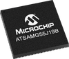
    • 49-lead WLCSP, 64-lead LQFP, 64-lead QFN
  • Temperature operating range
    • Industrial (-40° C to +85° C)
  • Peripheral Features
    • 8 flexible communication units supporting:
    • USART, SPI, or Two-wire Interface (TWI)
    • USB 2.0 Device and USB Host OHCI with On-chip Transceiver
    • 2 Inter-IC Sound Controllers (I2S)
    • 2 three-channel 16-bit Timer/Counters (TC) with capture, waveform, compare and PWM modes
    • 1 48-bit Real-Time Timer (RTT) with 16-bit prescaler and 32-bit counter
    • 1 RTC with calendar and alarm features
    • 1 32-bit Cyclic Redundancy Check Calculation Unit (CRCCU)
  • I/O
    • Up to 48 I/O lines with external interrupt capability (edge or level), debouncing, glitch filtering and on-die series resistor termination. Individually programmable open-drain, pull-up and pull-down resistor and synchronous output
    • Two PIO Controllers provide control of up to 48 I/O lines
  • Audio Features
    • 1 Pulse Density Modulation Interface (PDMIC) (supports up to two microphones)
    • Advanced Analog Features
  • 12-bit ADC Module:
    • One 8-channel ADC, 500 kSps Conversion Rate
    • 12-bit Resolution with Enhanced Mode up to 16 bits
    • Digital Averaging Function providing Enhanced Resolution Mode up to 16 bits
    • Integrated Multiplexer Offering Up to 8 Independent Analog Inputs
    • Standby Mode for Fast Wakeup Time Response
    • Asynchronous Partial Wake-up (Sleepwalking) on external trigger
  • Debugger Development Support
    • Serial Wire/JTAG Debug Port(SWJ-DP)
    • Debug access to all memories and registers in the system, including Cortex-M4 register bank when the core is running, halted, or held in reset.
    • Serial Wire Debug Port (SW-DP) and Serial Wire JTAG Debug Port (SWJ-DP) debug access.
    • Flash Patch and Breakpoint (FPB) unit for implementing breakpoints and code patches.
    • Data Watchpoint and Trace (DWT) unit for implementing watchpoints, data tracing, and system profiling.
    • Instrumentation Trace Macrocell (ITM) for support of printf style debugging.
    • IEEE1149.1 JTAG Boundary-scan on all digital pins.
  • Integrated Software Libraries and Tools
    • ASF-Atmel software Framework – SAM software development framework
    • Integrated in the Atmel Studio IDE with a graphical user interface or available as standalone for GCC, IAR compilers.
    • DMA support, Interrupt handlers Driver support
    • USB, TCP/IP, Wi-Fi and Bluetooth, Numerous USB classes, DHCP and Wi-Fi encryption Stacks
    • Image formats, file system & GUI library Middleware
    • RTOS integration, FreeRTOS a core component
Supplier's Site Datasheet

Technical Specifications

  Microchip Technology, Inc.
Product Category Microcontrollers (MCU)
Product Number ATSAMG55J19B
Data Bus 32 Bit
Clock Speed 120 MHz
Bits Other; 12-bit
Number 8
RAM 176 KB
Unlock Full Specs
to access all available technical data

Similar Products

 - 51-26192Z01-B - Rochester Electronics
Infineon Technologies AG
Specs
Data Bus 32 Bit
Life Cycle Stage Obsolete
Package Type QFP; Other; PG-LQFP-144-800
View Details
Embedded - Microcontrollers - ADUC842BCP32-5 - Lingto Electronic Limited
Specs
Data Bus 8 Bit; 8-Bit
View Details
Single Chip Microcomputer/Microcontroller >> Microcontroller Units (MCUs/MPUs/SOCs) - AM3352BZCZ80 - LCSC Electronics Technology (HK) Limited
Specs
Features LCD Driver
Package Type BGA
Operating Temperature 0 to 90 C (32 to 194 F)
View Details
Microcontrollers - 428480 - RS Components, Ltd.
RS Components, Ltd.
Specs
Data Bus 32 Bit; 32bit
ROM 256 KB
Package Type QFP; Other; LQFP
View Details